Basic Electrical Concepts


Some of the Basic Concepts include :
1. Electric Current
The rate of flow of electric charge through a point in a circuit is called electric current. Its unit is ampere, denoted by A,where 1 A = 1 coulomb per second.

2. Coulomb's Law
According to this law, the force of attraction or repulsion between stationary point charges is directly proportional to the product of the charges and inversely proportional to the square of the distance between them.


Where K = 9 X 
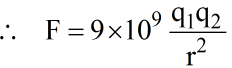 N
N

3. Electric Field
It is the region surrounding an electric charge or group of charges, in which another charge experiences a force of attraction or repulsion.
The electric field intensity at a point is defined as the force experienced by a unit positive test charge placed at that point.
The electric field E due to a point charge q at distance r is
E = k · q / r² (radially directed)

4. Electric Lines of Forces
- An electric line of force is a path along which a free isolated unit positive charge moves.
- Electric lines of force start from the positive charge and end at the negative charge.
- No two lines of force can intersect each other because if they do so, then at the point of intersection two tangents can be drawn which would mean two directions of force at that point which is impossible.
- Field lines tend to repel one another and spread out in regions where the field is weaker; they are denser where the field is stronger.
- Lines of force of uniform field are parallel.
- Lines of force leave the surface of the conductor normally.
5. Electric Flux
The total number of the electric field lines passing a given area through a given surface is known as the electric flux.

When the plane is irregular at an angle θ, then the projected area is Acosθ, and the total flux through this surface is given as-
Where,
E = Magnitude of the electric field.
A = Area of the surface through which the electric flux is calculated.
θ = The angle made by the axis and the plane that is parallel to the direction of flow of an electric field.
Unit of Electric Flux
- Common forms: V·m and N·m²/C.
- SI unit of Electric Flux: N · m²/C
Base unit: kg · m³ · s⁻³ · A⁻¹
6. Ohm's Law
According to this law if the physical state of the conductor (such as temperature) remains constant, then the current flowing through the conductor is directly proportional to the voltage applied i, e.
I α V .
I = 

- V is the potential difference measured across the conductor (in volts)I is the current through the conductor (in amperes)R is the constant of proportionality called resistance (in ohms)
- A graph between applied voltage and current is a straight line shows that it follows ohm's law.
- Ohm's law is valid for metallic conductors only.
7. Resistance
Resistance is the measure of opposition that a conductor offers to the flow of electric current.
Electrical resistance is directly proportional to length (L) of the conductor, material resistivity ρ and inversely proportional to the cross-sectional area (A). It is given by the following relation.
Note: The reciprocal of resistivity is called conductivity.
S/m (siemens per meter).
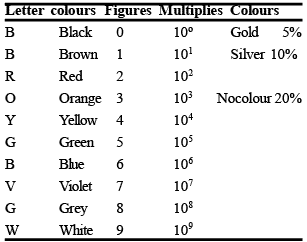
Colour Code for Resistances:
- Resistor colour codes, introduced by the Radio Manufacturers Association (RMA) in the 1920s, are used to represent resistance values, tolerance, and sometimes reliability on tiny resistors, typically up to one watt.
- These codes consist of 3 to 6 colour bands, with the first two indicating resistance value, the third as a multiplier, and additional bands specifying tolerance or reliability. This system simplifies reading resistance values without requiring printed numbers.
- These are usually carbon resistors, and the colour code is used to indicate resistance value.
- A carbon resistance has usually 4 concentric rings or bands A, B, C, D of different colours.

- The colour of first two bands A and B indicate the 1st two significant figures of resistance in ohms & those of 3rd band C indicate the decimal multiplies. The 4th band D (Which is either silver or gold) tells the tolerance.
- Sometimes only 3 colour bands are present.
- Standard colour order (digit values): Black(0), Brown(1), Red(2), Orange(3), Yellow(4), Green(5), Blue(6), Violet(7), Grey(8), White(9).
NOTE: B B ROY Great Britain Very Good Wife.
 Resistor colour table
8. Electric Potential
The electric potential at a point in an electric field is the ratio of the work done in bringing a test charge from infinity to that point to the magnitude of the test charge.
If the work done in moving a test charge q0 from infinity to that point against the field is W, then

9. Potential Gradient
The potential gradient is the rate of change of electric potential with respect to distance in an electric field. It is mathematically expressed as:
Mathematically,
E = - dV / dx


10. Electric Potential Energy
The electric potential energy of a system of charges is the work that has to be done in bringing these charges from infinity to near each other to form the system.
The potential energy of a system of charges q1 and q2 separated by a distance 'r' is
U = k · q1 · q2 / r
11. Capacitor
A capacitor is an electrical component that stores energy in the form of an electrostatic field between two or more conductors (plates) that are electrically isolated from each other.
- It functions similarly to a rechargeable battery ; they store energy when charged and release it when discharged.
- Capacitors come in various types, including small beads used in resonance circuits and larger ones for power factor correction.
- Despite their differences, all capacitors serve the same purpose of energy storage.
- Essentially, a capacitor consists of two or more conductive plates that are not connected or in contact with each other.
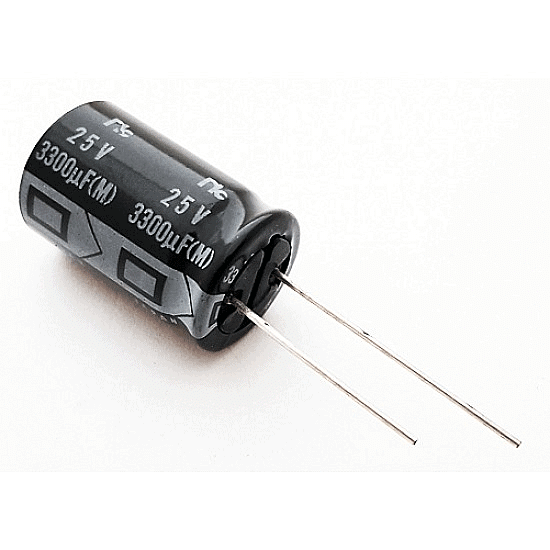 Practical Capacitor
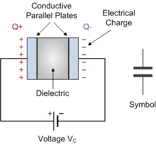 Capacitor Circuit diagram
12. Capacitance
- Capacitance refers to a capacitor's ability to store electrical energy and is measured in farads, a unit named after the British physicist Michael Faraday.
- It is defined as the ability of a capacitor to store one coulomb of charge to create a 1-volt potential difference.
 where Q is the stored charge and V is the potential difference between the plates.
 - Since the farad is a large unit, capacitance is often measured in smaller units such as microfarads (μF), nanofarads (nF) or picofarads (pF).
- For a parallel-plate capacitor with plate area A, plate separation d and dielectric permittivity ε,

where ε = εr · ε0 and ε0 = 8.85 × 10⁻¹² F/m. - SI Unit of Capacitance: Farad (F)
- Energy unit: Joule (J)
Energy stored in a capacitor:
Energy(E) = 
= 
= C. 

E = ½ Q² / C
E = ½ Q V
13. Inductor
An inductor is a component that does not require power to operate and is commonly used in various power electronic circuits. It is a passive electrical component that stores energy in the magnetic field created by current flowing through a coil of wire.
- Its main function is to store energy as magnetic energy when electricity flows through it.
- The unit of measurement for inductance is the Henry.
- The key characteristic of an inductor is its inductance, which is defined as the ratio of the voltage across it to the rate at which the current changes. This inductance arises from the magnetic field created around the coil of wire.
- Several factors influence the level of inductance, including:
- The shape of the coil.
- The number of turns and layers of wire in the coil.
- The spacing between the turns of wire.
- The permeability of the core material used.
- The size of the core itself.
One henry is defined as the inductance of a coil in which a change in current of one ampere per second induces a voltage of one volt.
Formula:The inductance L of an inductor is given by the formula:
Where:
- L = Inductance (in henries, H)
- N = Number of turns in the coil
- μ = Permeability of the core material (in henries per meter, H/m)
- A = Cross-sectional area of the coil (in square meters, m²)
- l = Length of the coil (in meters, m)
For a simple circuit, the induced voltage V is related to the rate of change of current by:
 Where:
- V = Induced voltage (in volts, V)
- L = Inductance (in henries, H)
- = Rate of change of current (in amperes per second, A/s)
Energy stored in Inductor:

= L. 
Try yourself: What is the unit of electric flux?
14. Inductance
Inductance results from the fact that a flow of current produces a magnetic field, because a changing magnetic field induces a current (Faraday's Law). The self-induced emf opposes the change in current.

(i) For RL Load (AC) :
For a sinusoidal applied voltage V = Vm sin ωt across an RL series circuit, the current I lags the voltage across the inductor by 90° in a purely inductive branch and lags the applied voltage by some angle (less than 90°) depending on the R/L ratio in an RL circuit.V=Vm sin wt


show I lags by 90º R-L Load phasor :-


(ii) For RC Load (AC):
In a circuit with a capacitive branch, the current leads the voltage by 90° for a purely capacitive element. In an RC circuit, the current leads the applied voltage by an angle depending on the R and C values.


Shows I leads by 90º in the pure capacitor case.
(iii) For RC phases:


(iv) For RLC Load:
In a series RLC circuit, the relative magnitudes of the inductive reactance (XL) and capacitive reactance (XC) determine whether the circuit behaves inductively, capacitively, or is in resonance.
Case 1: |VL| > |Vc| (inductive behaviour)

Case 2: |VL| < |Vc|(capacitive behaviour)


Case 3: |VL| = |Vc| (resonance condition)
Under resonance in a series RLC circuit, the net reactive voltage cancels and the applied voltage equals the resistive voltage:
V = VR
Phase angle Ø = 0,
cos Ø = 1 (unity power factor).
Note:- Reactive power is associated with energy storage in inductive and capacitive components and does not perform net work.
FAQs on Basic Electrical Concepts
| 1. What's the difference between voltage and current in basic electrical circuits? |  |
| 2. Why do I need to understand resistance if I just want to pass the SSC JE exam? | |
| 3. How do I tell the difference between active and passive electrical components? | |
| 4. What exactly happens when current flows through a conductor versus an insulator? | |
| 5. Can I use a single formula to solve all power-related questions in electrical circuits? | |


 | Explore Courses for Electrical Engineering (EE) exam |
 | Get EduRev Notes directly in your Google search |