Generation of Electrical Energy - 2 - Electrical Engineering (EE) PDF Download

Generation of Electrical Energy.
HYDRO ELECTRIC PLANTS
WATER POWER
- When water drops through a height, its energy is able to rotate turbines which are coupled to alternators.
The electric power
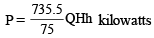
Where Q = Discharge, m3/sec H = Waterhead, m h = Overall efficiency of turbine alternator set
ADVANTAGES
- The useful life of a hydro-electric plant is around 50 years as compared to around 25-30 years for a steam station.
- The hydro plants do not require any fuel. Their operating costs are, therefore, low.
- There are no standby losses in hydro plants.
- They can be run up and synchronized in a few minutes. The load can be adjusted rapidly.
- Hydro plants are more robust as compared to steam plants.
- The maintenance cost of hydro plants is very low as compared to that of steam and nuclear plants.
- Efficiency of hydro plants does not reduce with age. On the other hand efficiency of steam plants decreases with age.
DISADVANTAGES
- The capital cost per kW of hydro plants is considerably higher than that of steam plants.
- H ydro pow er genera tion is dep endent on availability of water. In a dry year, the power generation is very small.
- The firm capacity of hydro plants is low and needs to be backed up by steam plants.
HYDROLOGY
Run-off
- Only a small part of rainfall can be used for power generation. A significant part of rain water evaporates, another part seeps into soil and forms the underground storage and some portion is taken up by the vegetation. The remaining water flows on the ground surface of the catchment area to form the steam and is known as run-off.
- The factors affecting run-off are – rainfall pattern, geology of the area, shape and size of catchment area the topography and nature of soil in the catchment area, amount of vegetation and weather conditions in the catchment are.
Stream Flow
- A knowledge of the quantity of water flowing in the stream and its variation with time over a period of many years is necessary to estimate the available energy.
- The stream flow meafurements are generally done by stream gauging at site and expressing m3/sec.
Hydrograph
- Hydrograph shows the variation of stream flow in m3/sec with time for a particular river site.
- It is similar to the chronological load curve.
Flow Duration Curve
- Flow duration curve is a re-arrangement of all the stream flow elements of a hydrograph in a descending order.
Mass Curve
- A mass curve indicates the total volume of runoff in cubic meters upto a certain time.
- The slope of the curve at any point shows the rate of flow at that time.
- If rain fall is uniform throughout the year, the mass curve would be a straight line having uniform slope.
Storage
- The main function of storage is to make water available during deficient flow times thus increasing the firm capacity of the station.
- Storage also means that the plant would produce more energy.
Pondage
- If the power is away from the storage reservoir, a smalll pond is needed near the power plant to meet the hourly changes in demand.
- The capacity of pond should be sufficient to cope with hourly change of 24 hours.
Site Selection The following factors have to be considered in the selection
Availability of Water
- The river run-off data pertaining to many years should be available so that an estimate of the power potential of the project can be made.
- The data should include the average flows, minimum and maximum flows and their periods.
Water Storage
- Because of wide fluctuations in stream flows, storage is needed in most hydro-projects to store water during high flow periods and use it during lean flow periods.
- The storage reservoir may be located near the power plant or some distance away from it.
Head of Water
- An increase in effective head reduces the quantity of water to be stored and handled by penstocks, screens and tubrines and therefore the capital cost of the plant is reduced.
Water Pollution
- Polluted water may cause excessives corrosion and damage to metallic structures.
- It is necessary to see that the water is of good quality and will not cause such troubles.
Sedimentation
- The capacity of storage reservoir is reduced due to the gradual deposition of silt.
- Silt may also cause damage to turbine blades.
Access to Site
- Construction of a hydro project involves transport of huge amount of cement, steel, other building material and heavy machinery.
- The site selected should be such that the railway line and roads can be constructed and material and machinery transported.
CLASSIFICATION
Run off River Plants Without Pondage
- These plants are located such that they use water as it comes, without any pondage or storage.
- There is no control on flow of water.
- During periods of high flows or low loads, water is wasted.
- During lean flow periods, the plant capacity is very low.
- During the periods of high flows, these plants can supply a substantial portion of base load.
Run off River Plant With Pondage.
- Pondage refers to storage at the plant to take care of hour to hour fluctuations in load on the station.
Remember:
- Such plants can serve as base load or peak load plants depending on the stream flow.
- When plenty of water is available, these plants can be used as base load plants.
- When stream flow decreases, these plants can be made to work as peak load plants.
- These plants offer maximum conservation of coal when operated in conjunction with steam plants
Reservoir Plants
- Most of the hydro-electric plants, belong of this category.
- When water is stored in a big reservoir behind a dam. it is possible to control the flow of water and use it most effectively.
- Storage increases the firm capacity of the plant.
Remember:
- The plant can be used as a base load plant or as a peak load plant depending on the water stored in the reservoir, the rate of inflow and the system load.
- Bhakra Plant in India are notable examples of reservoir plants.
According to Load Ba
Base Load Plants
- They feed the base load of the system and they supply almost constant load throughout and operate on a high load factor.
Note:
- Base load plants are usually of large capacity.
- Run off river plants without pondage and reservoir plants are used as base load plants.
Peak Load Plants
- Run off river plants with pondage can be used as peak load plants during lean flow periods.
- Reservoir plants can also be used as peak load plants.
- Peak load plants have large seasonal storage.
Classification According to Head Low Head Plants
- When water head is less than 30 m, the plant is called a low head plant.
- The power plant is located near the dam and therefore, no surge tank is needed.
Remember:
- Francis of Kaplan turbines are used.
Medium Head Plants
- When water head is between 30 m to 100 m, the plant is called a medium head plant.
- An open channel brings water from main reservoir to the fore-bay from where penstocks carry water to the turbines.
Remember:
- Francis or Kaplan turbines are used.
High Head Plants
- The plants operating at heads above 100 m are generally classified as high head plants.
Remember:
- Generally Francis turbines are used for heads below 200 m and Pelton turbines for still higher heads.
Storage Reservoir
- it is necessary to store water during excess flow periods so that the same may be used during lean flow periods.
- The storage reservoirs help in supplying water to the turbines according to the load on the plant.
Remember:
- Low head plants require very high storage reservoir.
- The capacity of storage reservoir depends on thedifference between run off during high and lean flows.
- Detailed hydrological studies over long periods are necessary to arrive at a suitable figure.
DAM
- The function of dam in a hydro electric project, is to create an artificial head and storage.
- It is the most expensive and important part of a hydro project.
Forbey
- It is an enlarged body of water at the intake to store water temporarily to meet the hourly load fluctuations.
Intake
- The function of intake is to provide a passage to water to flow into the water conduit, channel or penstock.
Surge Tank
- The function of the surge tank is to absorb these sudden changes in water requirements so as to prevent water hammer and vacuum.
Remember:
- The surge tank helps in stabilizing the velocity and pressure in the penstock and reduces water hammer and negative pressure (i.e. vacuum).
- It should be located as near the power house as possible. Some times it may be located underground also.
Penstock
- A penstock carries water from the water storage system to the turbine.
- A low pressure penstock may be a canal, flume or a steel pipe and the high pressure penstock consists of thick steel pipes. Each turbine has a separate penstock.
Spillway
- Every dam is provided with an arrangement to discharge excess water during floods this arrangement may be a spillway or a by-pass tunnel or conduit.
Tailrace
- A tail race is required to discharge the water leaving the turbine, into the river.
- It is necessary that the draft tube must remain water sealed all the time.
Remember:
- Impulse turbines do not need a draft tube and discharge water directly.
- The design and size of the tailrace should be such that water has a free exit and the jet of water, after it leaves turbine, has unimpeded passage.
HYDRAULIC TURBINES
- Hydraulic turbines convert the energy of water into mechanical energy which drives the alternators.
- They are highly efficient (efficiency exceeding 90° at full load), simple in construction, can be controlled easily and pick up load in a very short time.
- Hydraulic turbines can be classified into impulse and reaction turbines.
Specified Speed
- Specific speed of a turbine is the speed of a scale model of turbine which develops 1 metric h.p. under a head of 1 metre.

WhereNs = Specific speed in metric units N = Speed of turbine in rpm Pt = Output in metric h.p.
H = Effective head in metres Types of Turbines A classification of turbines according to range of head and specific speed is as under : Remember:
| Types of Turbine | Head | Specific speed (metric units) |
| Pelton | Above 200m | 10 - 50 |
| Francis | 30 m - 200m | 60 - 300 |
| Propeller | Less than 30m | 300 - 1000 |
Pelton Turbine
- It works under large head and low quantity of water.
- This turbine is not suitable for heads below 200 m.
- Its specific speed is in the range of 10-50.
Francis Turbine
- It develops power partly due to the velocity of water and partly due to the difference in pressure acting on the front and back of the runner buckets.
Remember:
- It is a reaction turbine suitable for medium heads and medium flows.
Propeller and Kaplan Turbines
- Propeller turbine is a reaction turbine suitable for low head and large quantity of water. It is suitable for heads below 30 m.
- A Kaplan turbine is a propeller turbine with adjustable blades, the advantage of adjustable blades being that a Kaplan turbine operates at high efficiency even under part load conditions.
Remember:
- The speed of Kaplan turbines is more than that of Francis turbines and lies in the range of 400-1500 rpm.
Bulb Turbines Remember:
- It is particularly useful for the low heads is the bulb turbine unit and tidal schemes.
- A bulb turbine is an axial flow turbine, so called because water flows through the machine coaxial with the turbine shaft.
Advantages:
- They can be used at very low and widely varying heads and have high efficiency due to axial straight flow.
- The cos t of civil engineering w orks is considerably reduced when bulb turbines are used.
- They are smaller, faster and easier to build than other types and are cheaper in capital cost than Kaplan turbines.
- The bulb turbines are universally used for small hydro schemes.
Disadvantage :
- It is difficult to access the generator for maintenance and the generator has low inertia
PUMPED STORAGE PLANTS
- A pumped storage plant is a special type of plant meant to supply peak loads.
- During peak load period, water is drawn from the head water pond through the penstock and generates power for supplying the peak load.
- During the off-peak period, the same water is pumped back from the tail water pond to the head water pond so that this water may be used to generate energy during the next peak load period.
Remember:
- Peak loads can be supplied at a lesser cost than that incurred when these loads are supplied by steam and nuclear plants. Pumped storage plants need a starting time of only 2 to 3 seconds and can be loaded fully in about 15 seconds.
- The load factor of steam and nuclear plants is increased thus ensuring their efficient and economic operation.
- They can be used for load frequency control.
NEUCLEAR POWER PLANTS
The nuclear power is the only source which can supply the future energy demands of the world.
MAIN ADVANTAGES
- The amount of fuel used is small. Therefore, the fuel cost is low.
- There are no problems of fuel transportation storage etc.
- Nu clear pl ant s need less area than the conventional steam plants.
- Greater nuclear power production leads to conservation of coal, oil etc.
- The initial capital cost of nuclear plants is very high.
ENERGY MASS RELATIONSHIP
- Einstein’s theory of relativity shows that mass and energy are interchangeable. If mass is destroyed, energy is produced and mass can be produced by expenditure of energy.
- Energy mass relation E = mc2 where E = Energy is Joules m = Mass in kilogram c = Velocity of light (3 × 10⁸ m/sec)
- Mass is represented in atomic mass units (amu).
- One amu equals one-twelfth the mass of a carbon atom.
- Mass of proton and neutron is each equal to 1 amu.
- 1 amu = 1.6604 × 10⁻²⁴ grams.
- One amu mass is equivalent to 931.1 MeV.
ISOTOPES
- Elements, having same atomic number but different mass numbers, are called isotopes.
- Uranium exists as 92U235, 92U235 and 92U238.
The natural uranium contains 99.23% of 92U238.
RADIOACTIVITY
- Isotopes of thorium, radium and uranium are unstable. They disintegration of an unsable nucleus is called radioactivity.
- Artificial radioactivity is often produced by subjecting nuclei to neutron bombardment. The radiations emitted in the process of radioactive decay are :
- a particles, b particles, g arays and neutrons.
- a particles are nuclei of the belium atom of the helium atom 2He4.
Examples
92
U238 ® 2He4 + 90Th234 94
Pu239 ® 2He4 + 92Th235 CANNING
The canning materials are aluminium, magnesium, beryllium and stainless steel.
- The fuel element, in a nuclear reactor, is canned so that the fuel does not contaminate the coolant.
- Canning eliminates radiation hazards.
- The choice of canning material depends largely on the fuel used in the reactor.
COOLANT
- Coolant removes heat from the fuel elements and transfers it to water.
- A good coolant should not absorb neutrons, should be non-oxidizing non-toxic and non corrosive and have high chemical and radiation stability. It should have good heat transfer capability.
Remember:
- The materials used as coolants are carbon dioxide, liquid metal, water and heavy water.
MODERATOR
- The purpose of moderator material is to slow down the fast neutrons.
- The fast neutrons collide with the nuclei of moderator material, loose their energy and get slowed down.
Properties required for a good moderator :
- It must not react with neutrons because neutrons captured in nuclear reactions are lost to the fission process and this leads to an inefficient reactor.
- It should be inexpensive
- It should be chemically inert and should not corrode or erode.
- It should not undergo harmful physical or chemical changes when bombarded by neutrons.
- ¡ The average neutron-nucleus collision should lead to large neutron energy loss.
FISSILE AND FERTILE MATERIALS
- The materials which are known to undergo neutron fission are U235, U233 and Pu239. These are fissile materials U235 is the only one occurring in nature (as 0.72% of the natural uranium) and has served as the basis of nuclear energy programme.
- U238 and Th232 are not fissionable. However these two materials can be converted into Pu239 and U233 resepctively. These two materials (i.e. U238 and Th232) are known as fertile materials.
NUCLEAR REACTORS
Advanced Gas Cooled Reactor (AGR)
- This reactor uses uranium dioxide as fuel.
- The reactor can be refuelled on load and this is an operational advantage.
- The coolant is CO2.
- A gas cooled reactor is economical when load factor is more than 75%.
- Its overall efficiency is about 40%.
Magnox Reactor
- This is also a gas colled reactor and similar to AGR.
- It uses natural uranium as fuel.
- The overall efficiency is about 30%.
Pressurised Water Reactor (PWR)
- The fuel used in PWR is enriched uranium oxide, clad in zinc alloy.
- Pressurized water is used both as coolant and moderator.
- One of the main drawbacks of this reactor is the design of high strength pressure vessel.
- The advantage is that steam supplied to the turbine is completely free from contamination.
- The overall efficiency is about 33%.
Boiling Water Reactor (BWR)
- BWR also uses enriched uranium oxide as fuel.
- The advantages of this reactor include a small size pressure vessel,high steam pressure and simple construction.
- Ordinary water is used both as coolant and moderator.
- The overall efficiency is about 33%.
FAQs on Generation of Electrical Energy - 2 - Electrical Engineering (EE)
| 1. What is electrical energy generation? |  |
| 2. What are the different methods of electrical energy generation? | |
| 3. What are the advantages of renewable energy sources for electrical energy generation? | |
| 4. What are the challenges in electrical energy generation from renewable sources? | |
| 5. Can electrical energy generation from renewable sources replace traditional fossil fuel-based generation? | |


Exam
,ppt
,practice quizzes
,Generation of Electrical Energy - 2 - Electrical Engineering (EE)
,video lectures
,Generation of Electrical Energy - 2 - Electrical Engineering (EE)
,Generation of Electrical Energy - 2 - Electrical Engineering (EE)
,Summary
,shortcuts and tricks
,Extra Questions
,mock tests for examination
,Free
,Semester Notes
,Sample Paper
,Previous Year Questions with Solutions
,Important questions
,past year papers
,Viva Questions
,Objective type Questions
,study material
,MCQs
;


Generation of Electrical Energy - 2 Free PDF Download
Importance of Generation of Electrical Energy - 2
Generation of Electrical Energy - 2 Notes
Generation of Electrical Energy - 2 Electrical Engineering (EE) Questions
Study Generation of Electrical Energy - 2 on the App
|
© EduRev
|
Education Revolution
|


|


