Gain Margin and Phase Margin - Electrical Engineering (EE) PDF Download

Gain Margin and Phase Margin
The Bode stability criterion states that the maximum value of the controller gain that can be chosen for stable closed loop response is called the ultimate gain Ku. In other words, the value of controller gain must always be less than Ku in order to ensure stability. The gain margin (GM) is a design parameter such that 79
79
Gain margin should always be chosen as greater than one (GM>1) to ensure stability .
Gain margin acts as a safety factor for model uncertainty. Since process parameters such as gain, time constant and dead time can never be estimated exactly, a safety factor of magnitude more than one is necessary for stable operation. For relatively well modeled processes, a low safety factor will be acceptable whereas poorly modeled processes need higher safety factors. For an example, let us choose GM=2 for the process we have discussed above (eq.71), the design value of the controller gain is Kc = 10.8 = 5.4; suppose there exists a modeling error of 50% in estimating the dead time of the process and the true value of the dead time is 0.45 instead of 0.3, then the revised value of crossover frequency is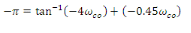 80
80
or,  , and the corresponding Ku = 7.3 which is still higher than the designed value of Kc = 5.4. The system is still stable despite the error by 50% we made in estimation of dead time of the process.
Phase margin is another safety factor which is used for controller design. Here we are interested to compute a frequency  that satisfies the following expression,
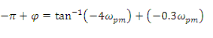 81
81
 is called phase margin (PM) and it is the extra phase lag needed to destabilize a system. For an example, let us choose
  .
.  can be calculated from the following expression
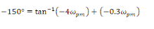 82
82
or,  . The gain is designed from the expression
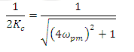 83
83
or, Kc = 7.44 Suppose there exists a modeling error of 50% in estimating the dead time of the process and the true value of the dead time is 0.45 instead of 0.3,then the phase lag encountered by the process would be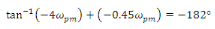 84
84
hich is 2° more than the safety limit for stability. Hence, the phase margin of  is not sufficient for handling 50% error in dead time estimation. It is left to the reader to verify that a phase margin of 45° will suffice for handling 50% error in dead time estimation.
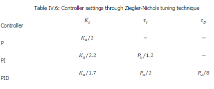
Ziegler Nichols Tuning technique
Unlike process reaction curve method which uses open loop response data, Ziegler Nichols tuning technique uses closed loop response data. The following settings are given by this technique for feedback controllers:
Nyquist Stability Criterion
The Bode stability criterion is valid for systems where amplitude ratio and phase shift decreases monotonically with ω. Nyquist stability criterion does not have any such limitation and is applicable in more general sense. The criterion states that:
If open-loop Nyquist plot of a feedback system encircles the point (-1,0) as the frequency ω varies from -∞ to +∞ the closed loop response is unstable.
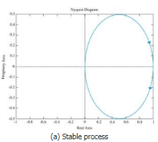
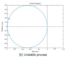
Fig. IV.16: Example of systems for studying Nyquist stability criterion
FAQs on Gain Margin and Phase Margin - Electrical Engineering (EE)
| 1. What is gain margin and phase margin? |  |
| 2. How are gain margin and phase margin related to system stability? | |
| 3. How can gain margin and phase margin be calculated? | |
| 4. What are the implications of a low gain margin or phase margin? | |
| 5. How can gain margin and phase margin be improved in a system? | |


Objective type Questions
,Free
,video lectures
,mock tests for examination
,Previous Year Questions with Solutions
,Important questions
,Gain Margin and Phase Margin - Electrical Engineering (EE)
,Gain Margin and Phase Margin - Electrical Engineering (EE)
,ppt
,past year papers
,Sample Paper
,Semester Notes
,Exam
,MCQs
,Extra Questions
,Summary
,practice quizzes
,study material
,shortcuts and tricks
,Viva Questions
,Gain Margin and Phase Margin - Electrical Engineering (EE)
;


Gain Margin and Phase Margin Free PDF Download
Importance of Gain Margin and Phase Margin
Gain Margin and Phase Margin Notes
Gain Margin and Phase Margin Electrical Engineering (EE) Questions
Study Gain Margin and Phase Margin on the App
|
© EduRev
|
Education Revolution
|


|


