Data Selectors & Multiplexers | Analog and Digital Electronics - Electrical Engineering (EE) PDF Download

Data Selectors & Multiplexers
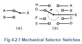
Simple way to connect multiple sources of information in analogue electronic systems is by using mechanical switches, such as those illustrated in Fig. 4.2.1. In example (a) a single pole double throw switch is used to select either input A or input B to be connected to output X. Example (b) shows a rotary selector switch that can multiplex any one of eight inputs to a single output.
In digital electronics, selecting multiple data sources can be performed by combinational logic circuits. Logic signals applied to one or more data select inputs initiate the selection of data, which may be steady logic levels or whole streams of digital information. Switching digital signals in this way is much faster and more reliable than using mechanical switch contacts. Digital data selectors and multiplexers are therefore a vital part of many digital systems. The names ‘data selector’ and ‘multiplexer’ are commonly interchanged, with multiplexers called data selectors and vice versa. If there is any difference, a circuit selecting between two inputs may be called a data selector, and more complex circuits combining multiple inputs into a single output, using various methods and existing in both digital and analogue forms, would be called multiplexers.
Basic Data Select (Multiplexer) Circuits
A simple data selector consisting of a single XOR gate was used in the 8 Bit Adder/Subtractor circuit shown in Figs. 4.1.5 and 4.1.6 in Module 4.1 to change the function of the circuit from addition to subtraction, but this was only required to select data B or its inverse B. The circuit shown in Fig. 4.2.2 however can select either of two completely independent data inputs.
The operation of Fig. 4.2.2 is quite straightforward and relies on ‘enabling’ either of a pair of NAND gates (1 and 2), but not both.
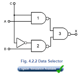
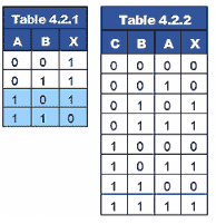
From the truth table for a NAND gate shown in Table 4.2.1 it can be seen that if one of the inputs (e.g. input A) is kept at logic 1, then the output will be the inverse of the other input. The gate is said to be enabled. If however input A is kept at logic 0, then the output will always be logic 1 whatever the state of the second input. The gate is therefore disabled, and the input cannot reach the output, even in inverted form. Gate 3 in Fig. 4.2.2 is simply combining the inputs from the other two gates. Table 4.2.2 illustrates the operation of Fig.4.2.2.
|
135 videos|167 docs|71 tests
|
FAQs on Data Selectors & Multiplexers - Analog and Digital Electronics - Electrical Engineering (EE)
| 1. What is a data selector and how does it work? |  |
| 2. What is the purpose of using a multiplexer in data selectors? | |
| 3. How are data selectors and multiplexers different from each other? | |
| 4. Can data selectors and multiplexers be used in combination with other digital circuits? | |
| 5. What are some common applications of data selectors and multiplexers? | |


Previous Year Questions with Solutions
,study material
,Extra Questions
,Data Selectors & Multiplexers | Analog and Digital Electronics - Electrical Engineering (EE)
,Objective type Questions
,Data Selectors & Multiplexers | Analog and Digital Electronics - Electrical Engineering (EE)
,past year papers
,practice quizzes
,Data Selectors & Multiplexers | Analog and Digital Electronics - Electrical Engineering (EE)
,Free
,Summary
,Sample Paper
,Viva Questions
,Semester Notes
,ppt
,mock tests for examination
,video lectures
,Exam
,Important questions
,shortcuts and tricks
,MCQs
;


Data Selectors & Multiplexers Free PDF Download
Importance of Data Selectors & Multiplexers
Data Selectors & Multiplexers Notes
Data Selectors & Multiplexers Electrical Engineering (EE) Questions
Study Data Selectors & Multiplexers on the App
|
© EduRev
|
Education Revolution
|


|


