Binary Comparators | Analog and Digital Electronics - Electrical Engineering (EE) PDF Download
| Table of contents |

|
| Equality Comparators |

|
| Magnitude Comparators |

|
| Medium Scale Integrated (MSI) Devices |

|
| Comparators in Cascade |

|
Binary comparators, also called digital comparators or logic comparators, are combinational logic circuits that are used for testing whether the value represented by one binary word is greater than, less than, or equal to the value represented by another binary word. Two basic types of comparator can be used.
• Equality comparators.
• Magnitude comparators.
Equality Comparators
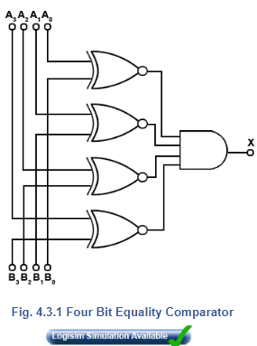
An equality comparator, such as that illustrated in Fig 4.3.1 is the simplest multi-bit logic comparator, and can be used for such circuits as electronic locks and security devices where a binary password consisting of multiple bits is input to the comparator to be compared with another preset word.
In Fig.4.3.1, a logic 1 will be present at the output if the two input words match, otherwise the output remains at 0. Therefore there is only one input combination that is correct, and the more bits the input words possesses, the more possible wrong combinations there are. With extra circuitry for counting, additional security may be provided by limiting the number of tries before the input is inhibited.
The circuit of the equality comparator consists of an exclusive NOR gate ( XNOR) per pair of input bits. If the two inputs are identical (both 1s or both 0s) an output of logic 1 is obtained.
The outputs of the XNOR gates are then combined in an AND qate the output of which will be 1, only when all the XNOR gates indicate matched inputs.
Magnitude Comparators
The magnitude comparator can also be used to indicate equality, but has a further two outputs, one that is logic 1 when word A is greater than word B, and another that is logic 1 when word A is less than word B. Magnitude comparators therefore form the basis of decision making in logic circuits. Any logical problem can be reduced to one or more (sometimes many) yes/no decisions based on a pair of compared values.
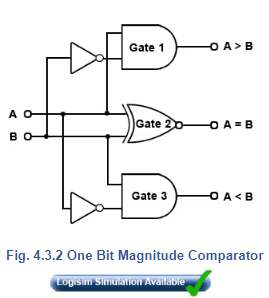
A simple 1-bit magnitude comparator is shown in Fig 4.3.2. Gate 1 produces the function A>B and gate 3 gives A<B while gate 2 is an XNOR gate giving an equality output.
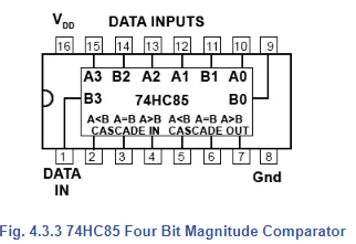
This basic circuit for a magnitude comparator may be extended for any number of bits but the more bits the circuit has to compare, the more complex the circuit becomes. Integrated circuit magnitude comparators are available that can be used to provide comparisons between multi-bit words. One such IC is the 74HC85CMOS 4- bit magnitide comparator from Philips Semicondutors (NXP) shown in Fig 4.3.3. This IC compares two 4-bit words and provides an output on pins 5, 6 and 7 that indicate whether the input words are equal, or if not, whether A or B has the higher numerical value.
Medium Scale Integrated (MSI) Devices
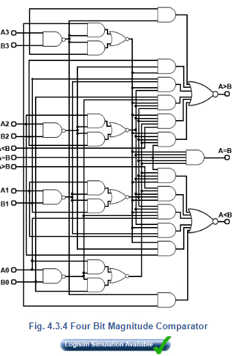
Fig. 4.3.4 shows a simplified circuit of a typical four−bit comparator, based on the 74HC85 IC with input and output buffers omitted. If you have been studying previous digital electronics modules with learnabout-electronics, you may notice that the level of complexity in Fig 4.3.4 is much greater than in previous circuits. In Module 2.1 it was stated that any digital circuit relies on just a few types of logic gate (AND, OR, NAND, NOR, NOT, XOR and XNOR) and even this list can be reduced by utilising just AND OR and NOT to obtain the other logic functions. Therefore more complex logic circuits still use combinations of these basic functions but it is the connections between them, and the rapid increase in the number of gates used that adds to the complexity
ICs like the 74HC85 are called 'Medium Scale Integrated' or MSI devices to distinguish them from SSI (Small Scale Integrated) devices such as the basic logic gate ICs studied in Module 2.1 and 2.2
Although these devices seem (and are!) complex is interesting to compare the number of individual transistors in this circuit with those used in the circuits described in earlier modules. Fig 4.3.4 shows 31 gates (not including the omitted input and output buffer gates), and each gate comprises about 4 transistors per gate giving a total transistor count for this typical MSI chip of well over 124 transistors, so it is not surprising that the circuit looks complex!
This one small IC then, contains more transistors than would be found for example in many analogue colour TV receivers, however this circuit does much less that would be required of the same number of transistors in a TV, and its operation is much easier to understand, especially if you already understand the operation of basic logic gates.
Note the outputs in Fig. 4.3.3, for A<B, A=B and A>B on pins 5, 6 and 7, and similar inputs on pins 2, 3 and 4, which enable a number of 74HC85 chips to be connected together to provide magnitude comparators for any word length.
Comparators in Cascade
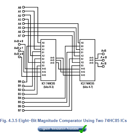
When two or more ICs are cascaded together, as shown in Fig. 4.3.5, the outputs of the first IC (representing the least significant 4 bits) are connected to the cascade inputs of the second IC and so on. The final result of the comparison appears on the three cascade outputs of the most significant 4-bit comparator.
To ensure a correct comparison, the cascade inputs of the first (least significant) comparator should be connected as follows:
A<B (pin 2) and A>B (pin 4) = logic 0.
A=B (pin 3) = logic 1.
This also applies to a single IC if only two 4-bit words are being compared.
|
135 videos|181 docs|71 tests
|
FAQs on Binary Comparators - Analog and Digital Electronics - Electrical Engineering (EE)
| 1. What is a binary comparator? |  |
| 2. How does a binary comparator work? |  |
| 3. What are the applications of binary comparators? |  |
| 4. Are there different types of binary comparators? |  |
| 5. Can binary comparators handle numbers of different bit lengths? |  |


