Electrical Engineering (EE) Exam  >  Electrical Engineering (EE) Test  >  Analog and Digital Electronics  >  Analog Electronics - 7 - Electrical Engineering (EE) MCQ

Analog Electronics - 7 for GATE EE and Digital - Free MCQ Test with solutions


MCQ Practice Test & Solutions: Analog Electronics - 7 (10 Questions)

You can prepare effectively for Electrical Engineering (EE) Analog and Digital Electronics with this dedicated MCQ Practice Test (available with solutions) on the important topic of "Analog Electronics - 7". These 10 questions have been designed by the experts with the latest curriculum of Electrical Engineering (EE) 2026, to help you master the concept.

Test Highlights:

  • - Format: Multiple Choice Questions (MCQ)
  • - Duration: 30 minutes
  • - Number of Questions: 10

Sign up on EduRev for free to attempt this test and track your preparation progress.

Analog Electronics - 7 - Question 1

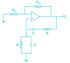
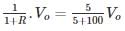
For the Wien-bridge oscillator circuit shown below, the condition for bridge balance is

Detailed Solution: Question 1

At oscillator frequency 
i.e. gain of non-inverting amplifier 
⇒ RB = 2RA

Analog Electronics - 7 - Question 2

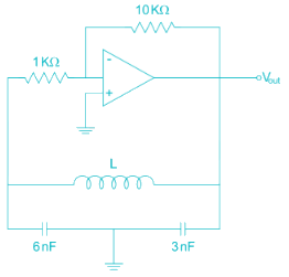
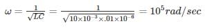
Find the value of inductance in (mH) in the oscillator shown below to achieve a frequency of oscillation = 100 KHz is

Detailed Solution: Question 2

*Answer can only contain numeric values
Analog Electronics - 7 - Question 3

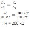
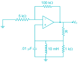
For the circuit shown in the figure the value of R to get oscillation of 100 kHz is ________ KΩ.


Detailed Solution: Question 3

The given oscillator is Colpitts’s oscillator

The condition for oscillation is

|Aβ|=1

A = -R2/R1

β=C2/C1

*Answer can only contain numeric values
Analog Electronics - 7 - Question 4

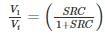
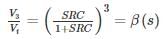
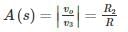
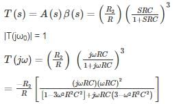
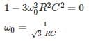
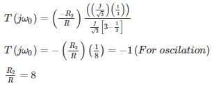
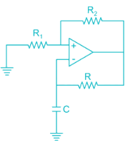
The figure shows a phase-shift oscillator circuit with voltage follower buffer stages.


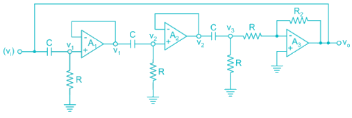
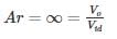
The value of R2/R required for sustained oscillations is _____.
[Assume ideal op-amps and neglect loading effect].


Detailed Solution: Question 4

  • The basic amplifier of the circuit is the op-amp A3.
  • The output of amplifier is connected to 3 stage RC filter.
  • Voltage followers eliminate loading effect of each stage.


Transfer function of first RC network

RC networks are identical and no loading effect

The amplifier A3 is connected in inverting mode

The loop gain is

Substitute real part of denominator to zero

At this frequency

Analog Electronics - 7 - Question 5

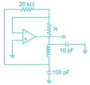
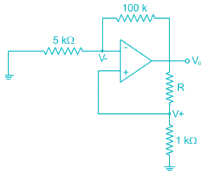
The value of R in oscillator circuit shown in a given circuit below is chosen such that it oscillates at an angular frequency of ω. The value of ω and the required value of R will respectively be

Detailed Solution: Question 5

Hartley oscillator


Amp with +ve F.B

Loop again AB = 1 + j0         

At oscillation

∠AB = 0 (no reactance XL = XC)

At frequency of oscillation look lies resistive Network


For ideal op amp

Use voltage division Rule

R + 1 = 21

R = 20 kΩ

R = 2 × 10⁴Ω 

*Answer can only contain numeric values
Analog Electronics - 7 - Question 6


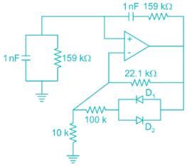
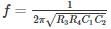
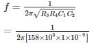
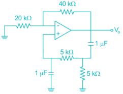
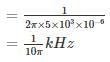
The frequency of oscillation of the circuit in kilohertz is ______ kHz.


Detailed Solution: Question 6

The given circuit is wein bridge oscillator.


R3 = R4 = 159 KΩ

C1 = C2 = 1 nF


= 103 HZ

= 1 KHZ

Analog Electronics - 7 - Question 7

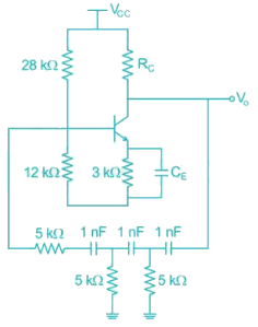
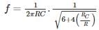
For the transistor oscillator circuit given below the frequency of oscillation is 8.5 kHz. The value of the collector resistor approximately is


Detailed Solution: Question 7

In a transistor phase shift oscillator the oscillation frequency


R, C are the resistor and the capacitor in phase shift circuit

RC is collector capacitance

⇒ RC = 2R = 10 kΩ 

*Answer can only contain numeric values
Analog Electronics - 7 - Question 8

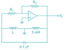
The oscillation frequency if the below-shown oscillator is 1 kHz then the value of ‘L’ is ______ mH


Detailed Solution: Question 8

The given oscillator is Hartley oscillator, where the oscillation frequency.


= 253.3 mH

Leq = L + 5 mA

⇒ L = 253.3 – 5

= 248. 3 mH

Analog Electronics - 7 - Question 9

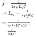
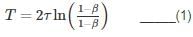
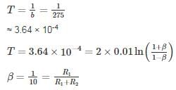
For the circuit shown the value of R1 and R2 such that the circuit generates oscillations of frequency 274 Hz is [Assume the time constant of the feedback RC network is 0.01 sec]

Detailed Solution: Question 9

Given figure is of A-stable multi-vibrator,

Time constant is given by

β = feedback factor

τ = time constant of feedback loop:

Option 3 satisfies the condition

*Answer can only contain numeric values
Analog Electronics - 7 - Question 10

The frequency of oscillation of the circuit shown below is ________ Hz.


Detailed Solution: Question 10

The given oscillator is Wien-bridge oscillator with R = 5 kΩ, C = 1 μF 

⇒ frequency of oscillation f = 1/2πRC

= 31.8 Hz

135 videos|182 docs|71 tests
Information about Analog Electronics - 7 Page
In this test you can find the Exam questions for Analog Electronics - 7 solved & explained in the simplest way possible. Besides giving Questions and answers for Analog Electronics - 7, EduRev gives you an ample number of Online tests for practice
135 videos|182 docs|71 tests
Download as PDF