Electrical Engineering (EE) Exam  >  Electrical Engineering (EE) Tests  >  Test: Power Systems- 2 - Electrical Engineering (EE) MCQ

Test: Power Systems- 2 - Electrical Engineering (EE) MCQ


Test Description

10 Questions MCQ Test - Test: Power Systems- 2

Test: Power Systems- 2 for Electrical Engineering (EE) 2024 is part of Electrical Engineering (EE) preparation. The Test: Power Systems- 2 questions and answers have been prepared according to the Electrical Engineering (EE) exam syllabus.The Test: Power Systems- 2 MCQs are made for Electrical Engineering (EE) 2024 Exam. Find important definitions, questions, notes, meanings, examples, exercises, MCQs and online tests for Test: Power Systems- 2 below.
Solutions of Test: Power Systems- 2 questions in English are available as part of our course for Electrical Engineering (EE) & Test: Power Systems- 2 solutions in Hindi for Electrical Engineering (EE) course. Download more important topics, notes, lectures and mock test series for Electrical Engineering (EE) Exam by signing up for free. Attempt Test: Power Systems- 2 | 10 questions in 30 minutes | Mock test for Electrical Engineering (EE) preparation | Free important questions MCQ to study for Electrical Engineering (EE) Exam | Download free PDF with solutions
Test: Power Systems- 2 - Question 1

When series reactor is used in generating stations, the fault current magnitude is

Detailed Solution for Test: Power Systems- 2 - Question 1

Fault current is inversely proportional to reactance of the network. Therefore with series reactor, the fault current magnitude is reduced. It is preferred in the generating stations in some special applications for limiting the current flowing through the low MVA rating circuit breakers.

*Answer can only contain numeric values
Test: Power Systems- 2 - Question 2

A surge of 200 kV travels along an overhead line towards its junction with a cable. The surge impedance for the overhead line and cable are 450 Ω and 60 Ω respectively. The magnitude of the surge transmitted through cable is – (in kV)


Detailed Solution for Test: Power Systems- 2 - Question 2

1 Crore+ students have signed up on EduRev. Have you? Download the App
Test: Power Systems- 2 - Question 3

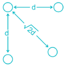
Ds is the GMR of each sub-conductor of a four sub-conductor bundle conductor and dd is the bundle spacing. What is the GMR of the equivalent single conductor?

Detailed Solution for Test: Power Systems- 2 - Question 3


*Answer can only contain numeric values
Test: Power Systems- 2 - Question 4


A transmission line having open circuit impedance and short circuit impedance parameters are respectively  Zoc = 900∠ − 30, ZSC = 400∠30∘ , Find the characteristic impedance of the line – (in Ω)


Detailed Solution for Test: Power Systems- 2 - Question 4

Test: Power Systems- 2 - Question 5

A three-phase, 50 Hz transmission line of length 120 km has a capacitance of 0.05/π μF/km It is represented as a π – model. The shunt admittance at each end of the transmission line will be

Detailed Solution for Test: Power Systems- 2 - Question 5

In π model, the shunt admittance at each end of the line is Y/2

= j300 × 10−6

= 300 × 10−6 ∠90mho

*Answer can only contain numeric values
Test: Power Systems- 2 - Question 6

A three-phase, 22 kV line feeds a per – phase load of 15 MW. If the impedance of the Line is Z = j 10Ω, then the value of load angle to maintain a line voltage of 22 kV at the load is_____ (in degrees)


Detailed Solution for Test: Power Systems- 2 - Question 6

Per phase sending and receiving end voltage 
We know that for a loss – less line (R = 0) real power is

*Answer can only contain numeric values
Test: Power Systems- 2 - Question 7

What is the maximum length (in km) for a single phase transmission line having a copper conductor of 0.8 cm2 cross-section over which 250 kW at unity power factor and at 3 kV are to be delivered?

The efficiency of transmission is 90%. The specific resistance as 2 μΩ-cm.


Detailed Solution for Test: Power Systems- 2 - Question 7

Receiving end power = 250 kW

Efficiency of transmission = 90%
Sending end power = 
Line losses = 277.78− 250 = 27.78kW
Line current, I

Let R be the resistance of one conductor.

Line losses = 2I2R
⇒27.78 × 10= 2(83.33)2R
⇒ R = 2 Ω

= 8 km

Test: Power Systems- 2 - Question 8

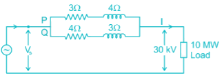
Two overhead Lines ‘P’ and ‘Q’ are connected in parallel to supply a load of 10 MW at 0.8 pf lagging. The resistance and reactance of line ‘P’ are 3 Ω and 4 Ω, respectively and of the Line, ‘Q’ is 4 Ω and 3 Ω respectively. The power supplied by the ‘P’ is

Detailed Solution for Test: Power Systems- 2 - Question 8

Impedance of Line P, ZP = 3 + j4 = 5∠53.13° Ω   

Impedance of Line Q, ZQ = 4 + j3 = 5∠36.86° Ω   


Total load supplied in kVA

Load supplied by Line P

= 6313.45 kVA at pf 0.708

Power supplied by Line P,

P = 6313.45 × 0.707 = 4.46 MW

*Answer can only contain numeric values
Test: Power Systems- 2 - Question 9

The load on an installation is 600 kW, 0.8 lagging p.f. which works for 3000 hours per annum. The tariff is Rs. 100 per KVA plus 20 Paise per kWh. If the power factor is improved to 0.9 lagging by means of loss of free capacitors costing Rs. 60 per kVAR, calculate the annual cost saving (in Rupees). Allow 10% per annum for interest and depreciation on capacitors.


Detailed Solution for Test: Power Systems- 2 - Question 9

D = 600 kW

Cosϕ1 = 0.8

Cosϕ2 = 0.9

Loading KVAR taken by the capacitors.

= P (tanϕ1 – tanϕ2)

= 600 (tan (cos-1(0.8)) – tan (cos-1 (0.9)))

= 159.41 KVAR

Annual cost before p.f. correction

Maximum KVA demand = 600/0.8=750

KVA demand charges = 750 × 100 = 75,000

Units consumed per annum = 600 × 3000 = 1800000 kWh

Energy charges per year = 0.2 × 1800000 = 360000

Total annual cost = 75000 + 360000 = 435000

Annual cost after p.f. correction

Maximum KVA demand =600/0.9 = 666.67

KVA demand charges = 666.67 × 100 = 66, 667

Energy charges = 360000

Capital cost of capacitors = 60 × 159.41 = 9564.6

Annual interest and depreciation = 0.1 × 9564.6 = 956.46

Total annual cost = 66667 + 360000 + 956.46 = 427623. 46

Annual saving = 435000 – 427623.46 = 7376.54

Test: Power Systems- 2 - Question 10

Two generators rated 250 MW and 400 MW are operating in parallel. The droop characteristics of the governors are 4% and 6% respectively.if a load of 450 MW is share between them. What will be the system frequency? Assume nominal system frequency is 60 Hz and no governing action.

Detailed Solution for Test: Power Systems- 2 - Question 10

Let, Load on generator 1 = x MW

Load on generator 2 = (450 – x) MW

Reduction in frequency = Δf

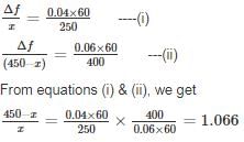
Now,


∴ x = 217.81 MW (load on generator 1)

450 – x = 232.18 MW (load on generator 2)

and Δf = 2.09Hz

∴ System frequency = (60 – 2.09) = 57.909 Hz.

Information about Test: Power Systems- 2 Page
In this test you can find the Exam questions for Test: Power Systems- 2 solved & explained in the simplest way possible. Besides giving Questions and answers for Test: Power Systems- 2, EduRev gives you an ample number of Online tests for practice

Top Courses for Electrical Engineering (EE)

Download as PDF

Top Courses for Electrical Engineering (EE)