Physics Exam  >  Physics Tests  >  Digital Electronics MSQ - Physics MCQ

Digital Electronics MSQ - Physics MCQ


Test Description

10 Questions MCQ Test - Digital Electronics MSQ

Digital Electronics MSQ for Physics 2024 is part of Physics preparation. The Digital Electronics MSQ questions and answers have been prepared according to the Physics exam syllabus.The Digital Electronics MSQ MCQs are made for Physics 2024 Exam. Find important definitions, questions, notes, meanings, examples, exercises, MCQs and online tests for Digital Electronics MSQ below.
Solutions of Digital Electronics MSQ questions in English are available as part of our course for Physics & Digital Electronics MSQ solutions in Hindi for Physics course. Download more important topics, notes, lectures and mock test series for Physics Exam by signing up for free. Attempt Digital Electronics MSQ | 10 questions in 45 minutes | Mock test for Physics preparation | Free important questions MCQ to study for Physics Exam | Download free PDF with solutions
*Multiple options can be correct
Digital Electronics MSQ - Question 1

Most demultiplexers facilitate which type of conversion? 

Detailed Solution for Digital Electronics MSQ - Question 1

A demultiplexer sends a single input to multiple outputs, depending on the select lines. Demultiplexer converts single input into multiple outputs.

*Multiple options can be correct
Digital Electronics MSQ - Question 2

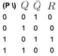
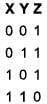
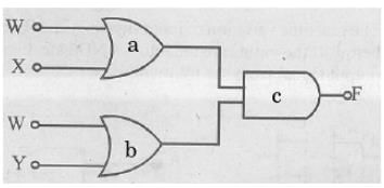
Which of the following sets of values given below satisfy the Boolean relation 

Detailed Solution for Digital Electronics MSQ - Question 2

The realization of the algebraic expression   in terms of logic gate is

Truth table.

Hence, (a), (c), (d)
The correct answers are: P = 0, Q = 0, R = 0, P = 1, Q = 0, R = 1, P = 1, Q = 1, R = 0

1 Crore+ students have signed up on EduRev. Have you? Download the App
*Multiple options can be correct
Digital Electronics MSQ - Question 3

The circuit shown in the figure can be used as :

Detailed Solution for Digital Electronics MSQ - Question 3


Hence, it is an integrator and a low-pass filter.
The correct answers are: Integrator, Low-pass filter

*Multiple options can be correct
Digital Electronics MSQ - Question 4

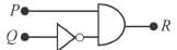
A pulse is applied to each input of an exclusive OR gate. One pulse goes HIGH at t = 0 and goes back LOW at t = 1 ms. The other pulse goes HIGH at = 0.8 ms and goes back LOW at t = 3 ms. The output pulse can be described as follows :

Detailed Solution for Digital Electronics MSQ - Question 4

Output is HIGH when only one of the input is high.
The correct answers are: It goes HIGH at t = 0 and back LOW at t = 0.8 ms, It goes HIGH at t = 1 ms and back LOW at t = 3 ms

*Multiple options can be correct
Digital Electronics MSQ - Question 5

If the output of a logic gate is 0 only when all its inputs are at logic 1, then which of the following are/is not the corresponding gate?

Detailed Solution for Digital Electronics MSQ - Question 5

Truth table is,

This is truth table for NAND gate.

The gate whose output is low if and only if all inputs are high, is NAND.

The logic NAND gate is a combination of a digital logic AND gate and a NOT gate connected together in series.

A NAND gate (NOT-AND) is a logic gate which produces an output which is false only if all its inputs are true; thus its output is complement to that of an AND gate. A LOW (0) output results only if all the inputs to the gate are HIGH (1); if any input is LOW (0), a HIGH (1) output results.

*Multiple options can be correct
Digital Electronics MSQ - Question 6

The following circuit  does not performs the operation of.

Detailed Solution for Digital Electronics MSQ - Question 6

If either V1 or V2 is high, we get a high in output, hence it each like an OR gate.
The correct answers are: NAND gate for a negative logic system, AND gate for a positive logic system, AND gate for a negative logic system

*Multiple options can be correct
Digital Electronics MSQ - Question 7

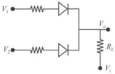
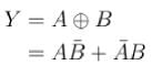
Which of the following options is false for a two input XOR gate?

Detailed Solution for Digital Electronics MSQ - Question 7


The truth table for XOR gate is

(b), (c), (d).
The correct answers are:


*Multiple options can be correct
Digital Electronics MSQ - Question 8

Inputs given to a logic gate are A and B and its output is X. If A = 1, B = 0, then X = 1. What type of gate this could be?

Detailed Solution for Digital Electronics MSQ - Question 8


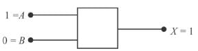
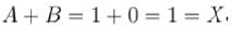
 clearly it follows OR gate. 


Thus, it also follows NAND gate 
  it is an AND gate 
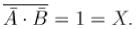
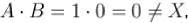
 it is not a NOR gate. 
Therefore, the correct options are (b, c)
The correct answers are: NAND, OR

Digital Electronics MSQ - Question 9

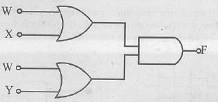
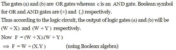
The diagram of a logic circuit is given below. Which of the following represents the output F?
211207

Detailed Solution for Digital Electronics MSQ - Question 9


*Multiple options can be correct
Digital Electronics MSQ - Question 10

A pulse is applied to each input of a 2 input NAND gate, one pulse goes high at t = 0 and goes back LOW at t = 1 ms. The other pulse goes high at f = 0.8 ms and goes Mark 0.00 out of 2.00 back LOW at t = 3 ms. The output pulse.
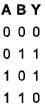
Detailed Solution for Digital Electronics MSQ - Question 10

A NAND gate is given by Truth table is.

It is low when both input signals are high otherwise it goes high.
The correct answers are: goes low at t = 0.8 ms, comes back high at t = 1 ms

Information about Digital Electronics MSQ Page
In this test you can find the Exam questions for Digital Electronics MSQ solved & explained in the simplest way possible. Besides giving Questions and answers for Digital Electronics MSQ, EduRev gives you an ample number of Online tests for practice
Download as PDF