Electronics and Communication Engineering (ECE) Exam  >  Electronics and Communication Engineering (ECE) Tests  >  Test: Basic Laws - 1 - Electronics and Communication Engineering (ECE) MCQ

Test: Basic Laws - 1 - Electronics and Communication Engineering (ECE) MCQ


Test Description

10 Questions MCQ Test - Test: Basic Laws - 1

Test: Basic Laws - 1 for Electronics and Communication Engineering (ECE) 2024 is part of Electronics and Communication Engineering (ECE) preparation. The Test: Basic Laws - 1 questions and answers have been prepared according to the Electronics and Communication Engineering (ECE) exam syllabus.The Test: Basic Laws - 1 MCQs are made for Electronics and Communication Engineering (ECE) 2024 Exam. Find important definitions, questions, notes, meanings, examples, exercises, MCQs and online tests for Test: Basic Laws - 1 below.
Solutions of Test: Basic Laws - 1 questions in English are available as part of our course for Electronics and Communication Engineering (ECE) & Test: Basic Laws - 1 solutions in Hindi for Electronics and Communication Engineering (ECE) course. Download more important topics, notes, lectures and mock test series for Electronics and Communication Engineering (ECE) Exam by signing up for free. Attempt Test: Basic Laws - 1 | 10 questions in 30 minutes | Mock test for Electronics and Communication Engineering (ECE) preparation | Free important questions MCQ to study for Electronics and Communication Engineering (ECE) Exam | Download free PDF with solutions
Test: Basic Laws - 1 - Question 1

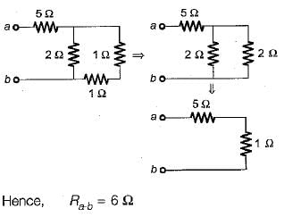
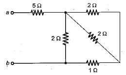
The equivalent resistance of the circuit shown in figure below across the terminals a-b will be
Detailed Solution for Test: Basic Laws - 1 - Question 1

On combining the resitances in parallel, equivalent circuit will reduce as shown in below.

Test: Basic Laws - 1 - Question 2

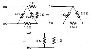
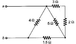
For the circuit shown below, the equivalent resistance across terminals a-b will be
Detailed Solution for Test: Basic Laws - 1 - Question 2

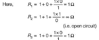
Hence, equivalent resistance is

1 Crore+ students have signed up on EduRev. Have you? Download the App
Test: Basic Laws - 1 - Question 3

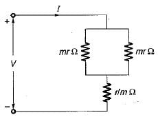
What is the value of m so that the current I in the circuit shown below is maximum?
Detailed Solution for Test: Basic Laws - 1 - Question 3

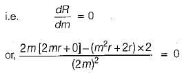
The equivalent resistance of the given circuit is

Hence, for current I to be maximum , R should be minimum.

Test: Basic Laws - 1 - Question 4

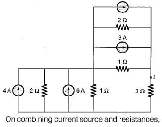
The given circuit shown below is converted to an equivalent voltage source V' connected in series with an equivalent resistance R'.
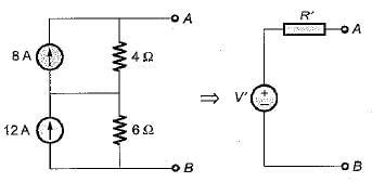
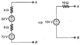
The values of V' and R' are respectively

Detailed Solution for Test: Basic Laws - 1 - Question 4

Converting the current sources into equivalent voltage sources, the circuit is reduced as shown below.

Test: Basic Laws - 1 - Question 5

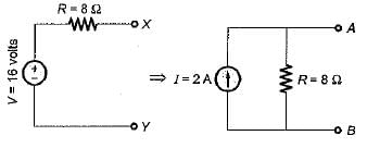
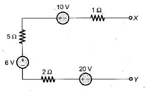
The equivalent current source for the circuit shown below will be represented as
Detailed Solution for Test: Basic Laws - 1 - Question 5

Equivalent voltage in the given circuit is

V= 6 + 2 0 - 1 0 = 16 volt

And equivalent resistance is R = 1 + 5 + 2 = 8 Ω

Test: Basic Laws - 1 - Question 6

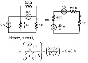
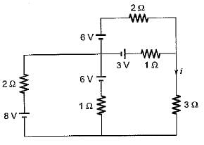
Assuming the batteries to be ideal voltage sources in the figure shown below, the value of current i is
Detailed Solution for Test: Basic Laws - 1 - Question 6

Converting all the voltage sources into equivalent current sources using source transformation, the equivalent circuit will be reudced as shown below.

Test: Basic Laws - 1 - Question 7

Two 100 W, 220 V bulbs are required to be connected across a 400 volts supply. The value of resistance to be inserted in the line so that the voltage across the bulbs does not exceed 220 V is

Detailed Solution for Test: Basic Laws - 1 - Question 7

Total power drawn from the circuit = 2 x 100 = 200 watts

Hence, supply current is

Let R be the series resistance to be inserted in the circuit such that the voltage across the bulbs is 220 V.

Applying KVL , we get

Test: Basic Laws - 1 - Question 8

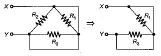
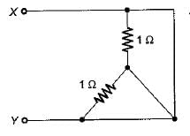
The equivalent resistance across the terminal X-Y for the circuit shown below is
Detailed Solution for Test: Basic Laws - 1 - Question 8

Converting the star-connected resistors into Δ equivalent, the given circuit is reduced as shown below.

Hence, equivalent resistance between terminals Xand Y is

Test: Basic Laws - 1 - Question 9

Assertion ( A ) : KCL states that at any node of a circuit, at any instant of time, the sum of incoming currents is equal to the sum of outgoing currents.
Reason (R): KCL indicates the law of conservation of energy.

Detailed Solution for Test: Basic Laws - 1 - Question 9

KCL is based on law of conservation of charge while KVL is based on law of conservation of energy.

Test: Basic Laws - 1 - Question 10

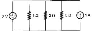
The total power absorbed in the circuit below is

Detailed Solution for Test: Basic Laws - 1 - Question 10

The current through the resistors will purely depend upon the voltage source of 2V connected a cross them . Let the currents i1 , i2  and i3 respectively flowing through the resistors of 1Ω,  2Ω and 5Ω.

Information about Test: Basic Laws - 1 Page
In this test you can find the Exam questions for Test: Basic Laws - 1 solved & explained in the simplest way possible. Besides giving Questions and answers for Test: Basic Laws - 1, EduRev gives you an ample number of Online tests for practice

Top Courses for Electronics and Communication Engineering (ECE)

Download as PDF

Top Courses for Electronics and Communication Engineering (ECE)