Electrical Engineering (EE) Exam  >  Electrical Engineering (EE) Test  >  GATE Mock Test Series 2027  >  Test: Block Diagrams - Electrical Engineering (EE) MCQ

GATE Electrical Engineering (EE) Test: Block Diagrams Free Online Test


MCQ Practice Test & Solutions: Test: Block Diagrams (10 Questions)

You can prepare effectively for Electrical Engineering (EE) GATE Electrical Engineering (EE) Mock Test Series 2027 with this dedicated MCQ Practice Test (available with solutions) on the important topic of "Test: Block Diagrams". These 10 questions have been designed by the experts with the latest curriculum of Electrical Engineering (EE) 2026, to help you master the concept.

Test Highlights:

  • - Format: Multiple Choice Questions (MCQ)
  • - Duration: 30 minutes
  • - Number of Questions: 10

Sign up on EduRev for free to attempt this test and track your preparation progress.

Test: Block Diagrams - Question 1

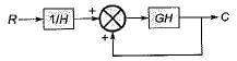
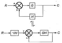
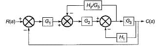
Which one of the following block diagrams in options given is equivalent to the below shown block diagram?

Detailed Solution: Question 1

The T.F. of the given block diagram can be reduced to: 
Its block diagram is shown below, where a closed loop feedback system is transformed into an unity feedback system and vice-versa,

Test: Block Diagrams - Question 2

Consider the following statements:
1. Transfer function is an expression which relates output to input in s-domain.
2. Transfer function gives information about the internal structure of the system.
3. A system can be represented by the block diagram if the transfer function of the system is known.
4. Block diagram is the flow of system variables from one block to another block represented by a single line.

Q. Which of the above statements is/are true?

Detailed Solution: Question 2

Transfer function does not gives information about the internal structure of the system. Hence, staement-2 is false.

Test: Block Diagrams - Question 3

What is the ratio C(s)/R(s) for the system shown in the figure below?

Detailed Solution: Question 3

On shifting the take-off point beyond the block G3 and combining blocks G2 and G3, the given block diagram is reduced as shown below.

The block diagram is further reduced as shown below:


Test: Block Diagrams - Question 4

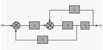
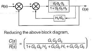
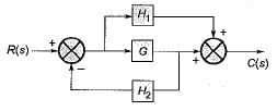
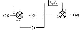
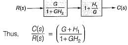
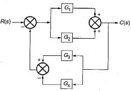
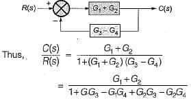
The transfer function C(s)/R(s) for the system described by the block diagram shown below is given by:

Detailed Solution: Question 4

On shifting the take-off point beyond block G, we have the reduced block diagram as shown below:

On further reducing the above block diagram, we get the block diagram as shown below.

Test: Block Diagrams - Question 5

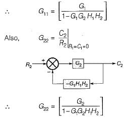
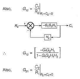
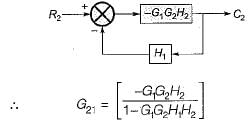
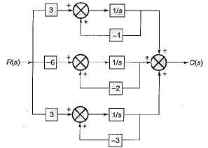
The transfer matrix for the multi input-multi output (MIMO) system represented by the block diagram shown below is given by

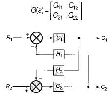
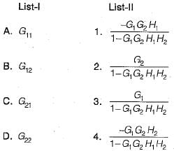
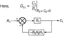
Match List-I with List-II and select the correct answer using the codes given below the lists:

Detailed Solution: Question 5


Test: Block Diagrams - Question 6

Consider the three block diagrams A, B and C shown below.


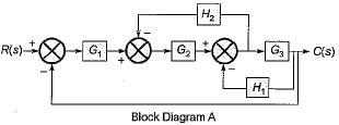
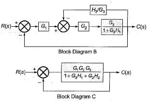
Q. Which one of the following statements is correct in respect of the above block diagrams?

Detailed Solution: Question 6

Shifting the take-off point after block G3 in block diagram-A, the reduced block diagram will be as shown below.

Reducing further, the block diagram is reduced as shown below.

Thus, the block diagrams A and B are equivalent to each other.
On further reducing the block diagram-B, we get the block diagram-C. Hence, all the three block diagrams A, B and C are equivalent to each other,

Test: Block Diagrams - Question 7

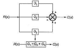
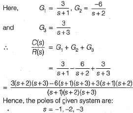
The poles of the transfer function C(s)/R(s) of the system represented by the block diagram shown below are located at 
 

Detailed Solution: Question 7

The given block diagram can be reduced as shown below.

Test: Block Diagrams - Question 8

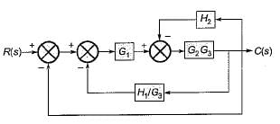
The transfer function C(s) / R(s) for the block diagram shown below is

Detailed Solution: Question 8

Combining the blocks in parallel, the block diagram is reduced as shown below.

Test: Block Diagrams - Question 9

The value of for the system described by the block diagram shown in figure below Is.

Detailed Solution: Question 9

The forward path consists of the block G1​. Therefore, the forward path transfer function is simply:

Tforward​ = G1

The system has a feedback loop involving G2​, H1​, and H2​.

  • The feedback loop introduces a feedback gain of:

Gfeedback​ = G2​H1​H2

The overall transfer function of a system with a feedback loop is given by:

Test: Block Diagrams - Question 10


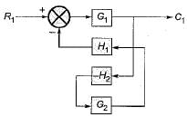
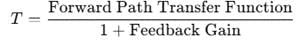
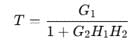
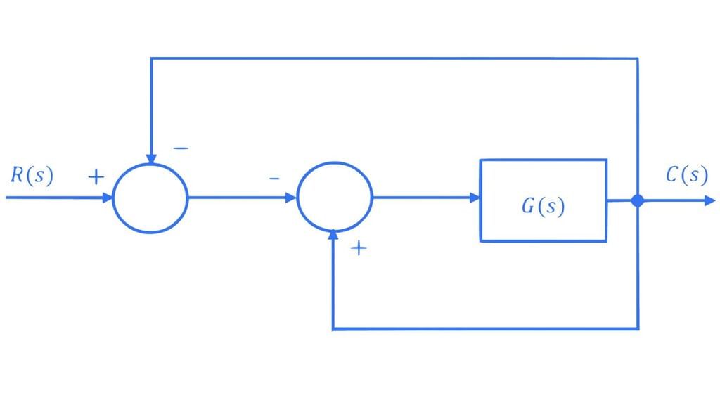
For the block-diagram shown in the figure, the transfer function C(s)/R(s) is

26 docs|247 tests
Information about Test: Block Diagrams Page
In this test you can find the Exam questions for Test: Block Diagrams solved & explained in the simplest way possible. Besides giving Questions and answers for Test: Block Diagrams, EduRev gives you an ample number of Online tests for practice
Download as PDF