Electronics and Communication Engineering (ECE) Exam  >  Electronics and Communication Engineering (ECE) Tests  >  Test: Diode Circuits - 1 - Electronics and Communication Engineering (ECE) MCQ

Test: Diode Circuits - 1 - Electronics and Communication Engineering (ECE) MCQ


Test Description

10 Questions MCQ Test - Test: Diode Circuits - 1

Test: Diode Circuits - 1 for Electronics and Communication Engineering (ECE) 2025 is part of Electronics and Communication Engineering (ECE) preparation. The Test: Diode Circuits - 1 questions and answers have been prepared according to the Electronics and Communication Engineering (ECE) exam syllabus.The Test: Diode Circuits - 1 MCQs are made for Electronics and Communication Engineering (ECE) 2025 Exam. Find important definitions, questions, notes, meanings, examples, exercises, MCQs and online tests for Test: Diode Circuits - 1 below.
Solutions of Test: Diode Circuits - 1 questions in English are available as part of our course for Electronics and Communication Engineering (ECE) & Test: Diode Circuits - 1 solutions in Hindi for Electronics and Communication Engineering (ECE) course. Download more important topics, notes, lectures and mock test series for Electronics and Communication Engineering (ECE) Exam by signing up for free. Attempt Test: Diode Circuits - 1 | 10 questions in 30 minutes | Mock test for Electronics and Communication Engineering (ECE) preparation | Free important questions MCQ to study for Electronics and Communication Engineering (ECE) Exam | Download free PDF with solutions
Test: Diode Circuits - 1 - Question 1

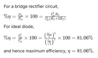
The theoretical maximum efficiency of a bridge rectifier circuit is

Detailed Solution for Test: Diode Circuits - 1 - Question 1

Test: Diode Circuits - 1 - Question 2

What is the primary reason a full-wave rectifier without a filter has a lower ripple factor compared to a half-wave rectifier?

Detailed Solution for Test: Diode Circuits - 1 - Question 2

The ripple factor measures AC fluctuations in a rectifier’s output. A full-wave rectifier has a lower ripple factor than a half-wave rectifier because it rectifies both halves of the AC input, producing an output with twice the frequency (e.g., 120 Hz for a 60 Hz input). This higher frequency results in smaller voltage fluctuations between peaks, reducing the ripple factor.
Option A: Correct, as higher frequency reduces ripple magnitude.

Test: Diode Circuits - 1 - Question 3

Assertion (A): The ripple voltage in a full-wave rectifier’s output can be minimized by adding a filter capacitor across the load.
Reason (R): The capacitor stores charge during voltage peaks and releases it during troughs, smoothing the output voltage.

Detailed Solution for Test: Diode Circuits - 1 - Question 3

The assertion is true: a filter capacitor reduces ripple voltage in a full-wave rectifier by smoothing the output. The reason is also true: the capacitor charges during voltage peaks and discharges during troughs, maintaining a steadier output voltage. The reason correctly explains how the capacitor minimizes ripple.

  • Option B: Correct, as both are true and R explains A.

Test: Diode Circuits - 1 - Question 4

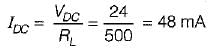
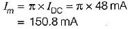
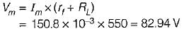
A half wave rectifier is used to supply 24 V DC to a resistive load of 500 Ω and the diode has a forward resistance of 50 Ω. What is the maximum value of the AC voltage required at the input?

Detailed Solution for Test: Diode Circuits - 1 - Question 4

Average value of load current,

Maximum value of load current,

Therefore, maximum AC voltage required at the input is

Test: Diode Circuits - 1 - Question 5

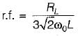
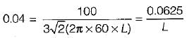
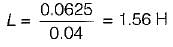
What is the value of inductance to be used in the inductor filter connected to a full-wave rectifier operation at 60 Hz to provide a DC output with 4% ripple for a 100 Ω load?

Detailed Solution for Test: Diode Circuits - 1 - Question 5

The ripple factor for an inductor filter is

∴  
or  

Test: Diode Circuits - 1 - Question 6

Diodes are used to clip voltages in circuits because they act as

Detailed Solution for Test: Diode Circuits - 1 - Question 6

Diodes are essential components in electronic circuits, primarily used to manage voltage levels. They perform this function by behaving like a voltage source under certain conditions. Here are the key points regarding their operation:

  • Clipping Voltage: Diodes can limit the maximum voltage in a circuit, preventing damage to other components.
  • Forward Bias: When a diode is forward-biased, it allows current to flow, effectively acting as a voltage source.
  • Reverse Bias: In reverse bias, the diode blocks current, protecting the circuit from excessive voltage.
  • Applications: They are commonly used in power supply circuits and signal processing.

In summary, diodes play a crucial role in controlling voltage levels by functioning as a voltage source under specific conditions, making them indispensable in many electronic applications.

Test: Diode Circuits - 1 - Question 7

When a capacitor is connected across the output terminals of a half or full-wave rectifier, the output voltage

Detailed Solution for Test: Diode Circuits - 1 - Question 7

When a capacitor is connected across the output terminals of a rectifier, the output voltage:

  • Essentially becomes a DC voltage.
  • Undergoes minimal fluctuations, smoothing out the signal.
  • Helps to store energy, providing a stable output.

This process is critical in converting the alternating current (AC) into a usable direct current (DC), which is essential for most electronic devices. The capacitor acts as a reservoir, filling in the gaps between the peaks of the rectified voltage and reducing the ripple effect.

Test: Diode Circuits - 1 - Question 8

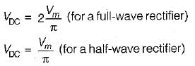
The equivalent DC output voltage of a full-wave rectifier is ____ the equivalent DC output voltage of a half-wave rectifier.

Detailed Solution for Test: Diode Circuits - 1 - Question 8

Test: Diode Circuits - 1 - Question 9

Assertion (A): A high value of resistor is connected across the diode in a clamper circuit for better performance.
Reason (R): If this resistor is not present, the circuit will respond to sudden decrease in the magnitude of the input pulse train, but the response to sudden increase in the amplitude will cause improper response.

Detailed Solution for Test: Diode Circuits - 1 - Question 9
  • Assertion (A): A high value of resistor is connected across the diode in a clamper circuit for better performance.

    • This statement is true. A high-value resistor is used in a clamper circuit to limit the current and ensure proper functioning. It helps in controlling the charge and discharge rates of the capacitor, which improves the overall performance of the circuit.
  • Reason (R): If this resistor is not present, the circuit will respond to a sudden decrease in the magnitude of the input pulse train, but the response to sudden increase in the amplitude will cause improper response.

    • This statement is also true. Without the resistor, the circuit may show an inappropriate response to the changes in the input signal, especially when there is a sudden increase in the amplitude. The resistor helps in stabilizing the response of the circuit to changes in the input signal by limiting the current flow and ensuring proper charge/discharge behavior.

Since both statements are true and the reason correctly explains the assertion, the correct answer is A: Both A and R are true and R is the correct explanation of A.

Test: Diode Circuits - 1 - Question 10

Assertion (A): Bridge arrangement is preferred over centre-tapped transformer arrangement for full-wave rectification.
Reason (R): The bridge arrangement improves the filtering action.

Detailed Solution for Test: Diode Circuits - 1 - Question 10

No filtering action is provided by bridge arrangement. Hence, reason is a false statement.

Information about Test: Diode Circuits - 1 Page
In this test you can find the Exam questions for Test: Diode Circuits - 1 solved & explained in the simplest way possible. Besides giving Questions and answers for Test: Diode Circuits - 1, EduRev gives you an ample number of Online tests for practice
Download as PDF