Electrical Engineering (EE) Exam  >  Electrical Engineering (EE) Test  >  GATE Mock Test Series 2027  >  Test: Introduction to Electrical & Electronics Measurements - Electrical Engineering (EE) MCQ

GATE Electrical Engineering (EE) Test: Introduction to & Electronics Measurements


MCQ Practice Test & Solutions: Test: Introduction to Electrical & Electronics Measurements (10 Questions)

You can prepare effectively for Electrical Engineering (EE) GATE Electrical Engineering (EE) Mock Test Series 2027 with this dedicated MCQ Practice Test (available with solutions) on the important topic of "Test: Introduction to Electrical & Electronics Measurements". These 10 questions have been designed by the experts with the latest curriculum of Electrical Engineering (EE) 2026, to help you master the concept.

Test Highlights:

  • - Format: Multiple Choice Questions (MCQ)
  • - Duration: 30 minutes
  • - Number of Questions: 10

Sign up on EduRev for free to attempt this test and track your preparation progress.

Test: Introduction to Electrical & Electronics Measurements - Question 1

in present day measurement systems

Detailed Solution: Question 1

Measurement by direct methods are not always possible, feasible and practicable. In most of the cases direct method of measurements are inaccurate because they involve human factors. Moreover, they are less sensitive. Due to these reasons use of direct method of measurement is limited while indirect methods are commonly used

Test: Introduction to Electrical & Electronics Measurements - Question 2

The use of electronic instruments is becoming more extensive because they have

Test: Introduction to Electrical & Electronics Measurements - Question 3

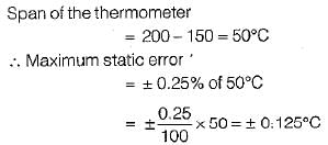
A thermometer is calibrated 150°C to 200°C. The accuracy is specified within ±0.25 percent of instrument span. The maximum static error is 

Detailed Solution: Question 3

Test: Introduction to Electrical & Electronics Measurements - Question 4

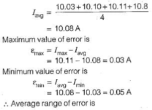
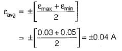
A set of independent current measurements were recorded as 10.03, 10.10, 10.08 and 10.11 A, The average range of error is 

Detailed Solution: Question 4

Average value of current is

Test: Introduction to Electrical & Electronics Measurements - Question 5

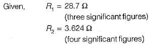
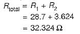
Two resistors R1, and R2 are connected in series with R1 = 28.7 Ω and R2 = 3.624 Ω. The total resistance to the appropriate number of significant figures can be written as

Detailed Solution: Question 5

For series connection,

Since one of the resistance (i.e. R1) is accurate only to three significant figures, therefore the result of R total has to be reduced to three significant figures. Hence, total resistance

Test: Introduction to Electrical & Electronics Measurements - Question 6

A Wheatstone bridge requires a change of 8 a in the unknown arm of the bridge to produce a change in deflection of 3 mm of the galvanometer. The deflection factor (scale factor) is

Detailed Solution: Question 6

  • The deflection factor (scale factor) relates the change in deflection to the change in resistance.
  • Given: A change of 8 Ω produces a deflection change of 3 mm.
  • Deflection factor = Change in Resistance / Change in Deflection = 8 Ω / 3 mm.
  • Calculate: 8 / 3 = 2.67 Ω/mm.
  • Thus, the deflection factor is 2.67 Ω/mm, which matches option B.

Test: Introduction to Electrical & Electronics Measurements - Question 7

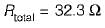
A moving coil voltmeter has a uniform scale with 100 divisions, the full scale reading is 200 V and 1/10 of a scale division can be estimated with a fair degree of certainty.The resolution of the instrument in volt is

Detailed Solution: Question 7

Test: Introduction to Electrical & Electronics Measurements - Question 8

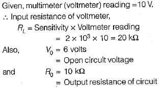
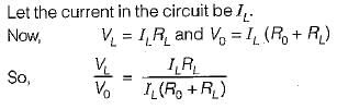
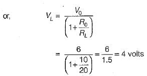
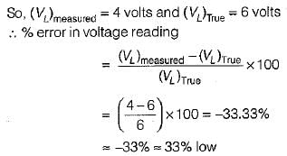
A multimeter having a sensitivity of 2 kΩ/V is used for the measurement of voltage across a circuit having an output resistance of 10 kΩ. The open circuit voltage of the circuit is 6 volts. The percentage error in multimeter reading when it is set to 10 volt is given by

Detailed Solution: Question 8

The circuit diagram for the measurement of voltage using multimeter is shown below:

Test: Introduction to Electrical & Electronics Measurements - Question 9

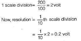
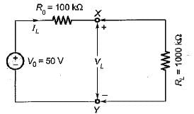
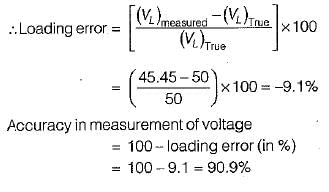
A 50 V range voltmeter is connected across the terminals X and Y of the circuit shown in figure below. The voltage across the terminals are measured both under open circuit and loaded conditions.

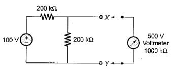
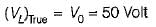
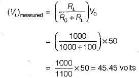
The accuracy in the measurement of voltage across the terminals X and Y in percent is

Detailed Solution: Question 9

The given circuit can be reduced to its Thevenin’s equivalent circuit as shown below.

True value of voltage across terminals X-Y is

Measured value of voltage across terminals X-Y is

Test: Introduction to Electrical & Electronics Measurements - Question 10

The number of significant figures in the two resistors having resistances 4 x 10⁶ kΩ and 0.345 kΩ are respectively

26 docs|247 tests
Information about Test: Introduction to Electrical & Electronics Measurements Page
In this test you can find the Exam questions for Test: Introduction to Electrical & Electronics Measurements solved & explained in the simplest way possible. Besides giving Questions and answers for Test: Introduction to Electrical & Electronics Measurements, EduRev gives you an ample number of Online tests for practice
Download as PDF