Civil Engineering (CE) Exam  >  Civil Engineering (CE) Tests  >  Test: Shear Force & Bending Moment - 1 - Civil Engineering (CE) MCQ

Test: Shear Force & Bending Moment - 1 - Civil Engineering (CE) MCQ


Test Description

10 Questions MCQ Test - Test: Shear Force & Bending Moment - 1

Test: Shear Force & Bending Moment - 1 for Civil Engineering (CE) 2024 is part of Civil Engineering (CE) preparation. The Test: Shear Force & Bending Moment - 1 questions and answers have been prepared according to the Civil Engineering (CE) exam syllabus.The Test: Shear Force & Bending Moment - 1 MCQs are made for Civil Engineering (CE) 2024 Exam. Find important definitions, questions, notes, meanings, examples, exercises, MCQs and online tests for Test: Shear Force & Bending Moment - 1 below.
Solutions of Test: Shear Force & Bending Moment - 1 questions in English are available as part of our course for Civil Engineering (CE) & Test: Shear Force & Bending Moment - 1 solutions in Hindi for Civil Engineering (CE) course. Download more important topics, notes, lectures and mock test series for Civil Engineering (CE) Exam by signing up for free. Attempt Test: Shear Force & Bending Moment - 1 | 10 questions in 30 minutes | Mock test for Civil Engineering (CE) preparation | Free important questions MCQ to study for Civil Engineering (CE) Exam | Download free PDF with solutions
Test: Shear Force & Bending Moment - 1 - Question 1

For the loaded beam shown in the figure, the correct shear force diagram is

Detailed Solution for Test: Shear Force & Bending Moment - 1 - Question 1

The shear force in the span BC will be zero. Hence the options A and B are incorrect. The shear force in the span AB and CD will be of opposite sign. Therefore, the option C is correct.

Test: Shear Force & Bending Moment - 1 - Question 2

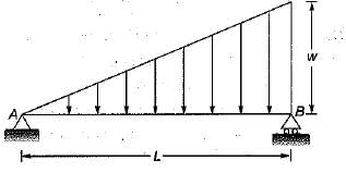
For the simply supported beam, shown in the figure below at what distance from the support A is the shear force zero?
Detailed Solution for Test: Shear Force & Bending Moment - 1 - Question 2


Let the point of zero shear force occur at section X-Xfrom left support A
∴ Shear force at X-X

∴ For zero shear force we have, 

∴ 

1 Crore+ students have signed up on EduRev. Have you? Download the App
Test: Shear Force & Bending Moment - 1 - Question 3

For the beam shown ih the given figure, the maximum positive bending moment is equal to the maximum negative bending moment. The value of L1 is

Detailed Solution for Test: Shear Force & Bending Moment - 1 - Question 3

The BM can be found from the area of SFD.
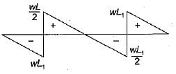
The shear force diagram is

Maximum negative, bending moment,

Maximum positive, bending moment,

For M1 = M2

Test: Shear Force & Bending Moment - 1 - Question 4

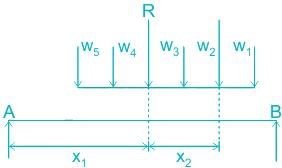
The maximum bending moment under a particular point load among a train of point loads crossing a simply Supported girder occurs at the location when that load is at 

Detailed Solution for Test: Shear Force & Bending Moment - 1 - Question 4

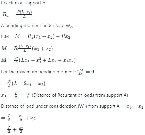
Position of Maximum Bending moment under a particular point load among a train of point loads:


Conclusion: The maximum bending moment under a particular point load among a train of point loads crossing a simply Supported girder occurs at the location when that load is at a point so that the load and the resultant should be equidistant from the mid-span.

Test: Shear Force & Bending Moment - 1 - Question 5

If a beam is subjected to a constant bending moment along its length then the shear force will

Detailed Solution for Test: Shear Force & Bending Moment - 1 - Question 5

The relation between shear force (V) and bending moment (M) is:

dM/dx = V

it means the slope of a bending moment diagram will represent the magnitude of shear force at that section.

Since the bending moment is constant along the length, therefore its derivative i.e. shear force is equal to zero at all sections along the beam.
There is no shear force between the loads and the bending moment is constant for that section along the length and vice-versa.

Additional Information

The relation between shear force (V) and loading rate (w) is:

dV/dx = w

it means a positive slope of the shear force diagram represents an upward loading rate.

The relation between loading rate and shear force can be written as:


Test: Shear Force & Bending Moment - 1 - Question 6

If the magnitude of shear force is constant, then the magnitude of the slope of bending moment curve is

Detailed Solution for Test: Shear Force & Bending Moment - 1 - Question 6

Explanation:

The following point should always be kept in mind while drawing SFD and BMD:

1. The rate of change of the shear force at any point on the axis of the beam is equal to the negative of the intensity of the distributed load at that same point.

i.e. w=−dV/dx

Here, negative sign represents that the loading is acting downward.

2. The rate of change of the bending moment at any point on the axis of a beam is equal to the shear force at that same point.

i.e. V=dM/dx

Calculation: -

From (2),

We have,

dM/dx=V=constant

Thus,

The magnitude of slope of moment diagram is also constant.

Test: Shear Force & Bending Moment - 1 - Question 7

Bending moment in the a beam is not a function of

Detailed Solution for Test: Shear Force & Bending Moment - 1 - Question 7

Bending moment (BM):

  • It is a measure of the bending effect that can occur when an external force (or moment) is applied to a structural element.
  • Failure can occur due to bending when the tensile stress exerted by a force is equivalent to or greater than the ultimate strength (or yield stress) of the element. However, although the mechanisms are different, a beam may fail due to shear forces before failure in bending.

Factors affecting bending moment:

1) Position and magnitude of the load

2) Type of beam: For a simply supported beam with UDL throughout the span, the maximum bending moment (WL2/8) is more as compared to a fixed beam(WL2/12) with the same loading condition.

3) Span of the beam: 

For example:

  • A simply supported beam subjected to a uniformly distributed load will have a maximum bending moment at the center.
  • Simply supported beams of two continuous spans subjected to uniformly distributed load would have a maximum sagging moment at the span center and maximum hogging moment at the supports.
Test: Shear Force & Bending Moment - 1 - Question 8

If the bending moment diagram for a simply suppoted beam is of the form as given in figure then the load acting on the beam is

Detailed Solution for Test: Shear Force & Bending Moment - 1 - Question 8


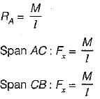
Span AC:

Span CB:

Test: Shear Force & Bending Moment - 1 - Question 9

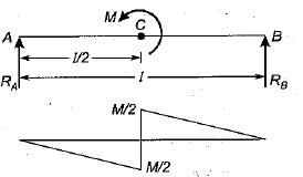
A beam is simply supported at its ends and is loaded by a couple at its mid-span as shown in figure. Shear force diagram for the beam is given by the figure

Detailed Solution for Test: Shear Force & Bending Moment - 1 - Question 9

Test: Shear Force & Bending Moment - 1 - Question 10

The point where the bending moment is zero after changing its sign is known as

Detailed Solution for Test: Shear Force & Bending Moment - 1 - Question 10

Points of zero bending moment

  • The points of contra flexure are points of zero bending moment, i.e. where the beam changes its curvature from hogging to sagging.
  • In a bending beam, a point of contra flexure is a location where the bending moment is zero (changes its sign).
  • In a bending moment diagram, it is the point at which the bending moment curve intersects with the zero lines.

Point of inflexion:

  • Point of inflexion is the point where the elastic deflection curve changes its curvature not bending moment diagram.
Information about Test: Shear Force & Bending Moment - 1 Page
In this test you can find the Exam questions for Test: Shear Force & Bending Moment - 1 solved & explained in the simplest way possible. Besides giving Questions and answers for Test: Shear Force & Bending Moment - 1, EduRev gives you an ample number of Online tests for practice

Top Courses for Civil Engineering (CE)

Download as PDF

Top Courses for Civil Engineering (CE)