Electrical Engineering (EE) Exam  >  Electrical Engineering (EE) Tests  >  Test: Inverters - 1 - Electrical Engineering (EE) MCQ

Test: Inverters - 1 - Electrical Engineering (EE) MCQ


Test Description

10 Questions MCQ Test - Test: Inverters - 1

Test: Inverters - 1 for Electrical Engineering (EE) 2024 is part of Electrical Engineering (EE) preparation. The Test: Inverters - 1 questions and answers have been prepared according to the Electrical Engineering (EE) exam syllabus.The Test: Inverters - 1 MCQs are made for Electrical Engineering (EE) 2024 Exam. Find important definitions, questions, notes, meanings, examples, exercises, MCQs and online tests for Test: Inverters - 1 below.
Solutions of Test: Inverters - 1 questions in English are available as part of our course for Electrical Engineering (EE) & Test: Inverters - 1 solutions in Hindi for Electrical Engineering (EE) course. Download more important topics, notes, lectures and mock test series for Electrical Engineering (EE) Exam by signing up for free. Attempt Test: Inverters - 1 | 10 questions in 30 minutes | Mock test for Electrical Engineering (EE) preparation | Free important questions MCQ to study for Electrical Engineering (EE) Exam | Download free PDF with solutions
Test: Inverters - 1 - Question 1

Assertion (A): For high power applications, inverters are used instead of transistors.
Reason (R): For high power applications, inverter is operated in active region.

Detailed Solution for Test: Inverters - 1 - Question 1

In low-power electronic circuits oscillators are used for converting dc power into ac power. These oscillator use transistors for converting dc voltage into sinusoidal ac voltage. Since transistor is used in active region, therefore there is substantial loss of power which decreases efficiency. In high power applications inverters are used instead of transistors and the inverters operate in saturation region or cut-off region. Thus, assertion is true but reason is false.

Test: Inverters - 1 - Question 2

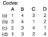
Match List-l (Type of Inverter circuits) with List-ll (Characteristics) and select the correct answer using the codes given below the lists: 
List-I 
A. Voltage Source Inverter
B. 120° Conduction Inverter
C. Current Source Inverter
D. 180°Conduction Inverter

List-II
1. Suitable for a load of low leakage impedance
2. Each device turns on at regular interval of 60º
3. Suitable for multi machine control
4. Preferable for a delta connected load
1 Crore+ students have signed up on EduRev. Have you? Download the App
Test: Inverters - 1 - Question 3

Consider the following statements associated with CSI and VSI:
1. In CSI, commutation is load dependent process.
2. Thyristorised current source fed inverter has inherent four quadrant operation.
3. In VSl dynamic braking is applicable during ac line failure.
4. MOSFET and transistor are more suitable for CSl compared to VSI.

Which of the statements given above is/are correct?

Detailed Solution for Test: Inverters - 1 - Question 3

• In CSI at light load, commutation time is considerably increased, which can restrict the highest frequency. Hence, commutation is load dependent process in CSI. Thus, statement-1 is correct.
• A VSl requires an additional line commutated converter for reverse power flow while it is hot so for a CSI i.e. a CSI has inherent four quadrant operation. Thus, statement-2 is correct.
• In VSl, dynamic braking is applicable during ac line failure. Thus, statement-3 is correct.
• MOSFET and transistor are more suitable for VSl not for CSI because in CSI large transient voltage is produced during commutation. Hence, statement-4 is not correct.

Test: Inverters - 1 - Question 4

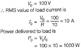
A single-phase half bridge inverter has supply voltage of 200 V. For a load resistance of 10 Ω, the output power is equal to

Detailed Solution for Test: Inverters - 1 - Question 4

Output is a square wave with an amplitude of 100V.
RMS value of a square wave is equal to its peak value.
So, rms value of output voltage is

Test: Inverters - 1 - Question 5

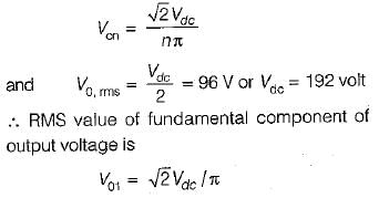
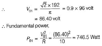
The single-phase half-bridge inverter has a resistive load of 10Ω and the centre-tap dc input voltage is 96 V. The fundamental power consumed by the load is

Detailed Solution for Test: Inverters - 1 - Question 5

The nth harmonic-component of output voltage is

Test: Inverters - 1 - Question 6

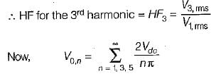
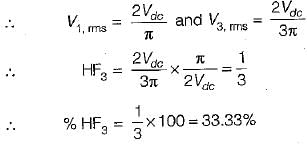
A single-phase half-bridge inverter has a resistive load of R = 3 Ω and the dc input voltage Vdc = 24 volts. The harmonic factor of the lowest order harmonic would be equal to 

Detailed Solution for Test: Inverters - 1 - Question 6

The lowest harmonic is third harmonic

Test: Inverters - 1 - Question 7

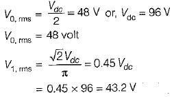
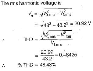
A single-phase transistorized bridge inverter has a resistive load of R = 3 Ω and the dc input voltage of 48 volts. The total harmonic distortion is approximately equal to

Detailed Solution for Test: Inverters - 1 - Question 7


Test: Inverters - 1 - Question 8

A full-bridge bipolar PWM inverter is fed from a 240 V battery and is driving an RL load. The fundamental output voltage for a modulation index of 0.8 is

Detailed Solution for Test: Inverters - 1 - Question 8

The fundamental output voltage for a modulation index of M is

Test: Inverters - 1 - Question 9

A current source inverter can be

Detailed Solution for Test: Inverters - 1 - Question 9

A CSl can be either load commutated or force commutated.

Test: Inverters - 1 - Question 10

The series-inverter control method is an-

Detailed Solution for Test: Inverters - 1 - Question 10

Voltage control of an inverter

The waveform of the output voltage obtained from a single-phase inverter is rectangular in nature with an amplitude approximately equal to the input dc voltage.

However, in many applications, the output voltage of the inverter needs to be controlled due to the following reasons:

  • The voltage required by ac loads may be constant or adjustable. 
  • In motor control applications, inverters handle the control of circuit voltage along with frequency so that the saturation of motor magnetic circuits is avoided.
  • Voltage control of inverters is employed in order to compensate for changes in input dc voltage.

Basically, there are three techniques by which the voltage can be controlled in an inverter. They are:

1. External Control of AC Output Voltage

  • This method is also known as the series-inverter control method.
  • In this method of control, an ac voltage controller is connected to the output of the inverter to obtain the required (controlled) output ac voltage. 
  • The voltage control is primarily achieved by varying the firing angle of the ac voltage controller that feeds the ac load.

2. External Control of DC Input Voltage

  • The external control of dc input voltage is a technique that is adapted to control the dc voltage at the input side of the inverter itself to get the desired ac output voltage at the load side.

3. Internal Control of Inverter

  • The output voltage of an inverter can be adjusted by employing the control technique within the inverter itself.
  • This control technique can be accomplished by the following two control methods: Series Inverter Control, and Pulse Width Modulation Control.
Information about Test: Inverters - 1 Page
In this test you can find the Exam questions for Test: Inverters - 1 solved & explained in the simplest way possible. Besides giving Questions and answers for Test: Inverters - 1, EduRev gives you an ample number of Online tests for practice

Top Courses for Electrical Engineering (EE)

Download as PDF

Top Courses for Electrical Engineering (EE)