Electrical Engineering (EE) Exam  >  Electrical Engineering (EE) Tests  >  Test: BJT Characteristics & Biasing- 2 - Electrical Engineering (EE) MCQ

Test: BJT Characteristics & Biasing- 2 - Electrical Engineering (EE) MCQ


Test Description

15 Questions MCQ Test - Test: BJT Characteristics & Biasing- 2

Test: BJT Characteristics & Biasing- 2 for Electrical Engineering (EE) 2024 is part of Electrical Engineering (EE) preparation. The Test: BJT Characteristics & Biasing- 2 questions and answers have been prepared according to the Electrical Engineering (EE) exam syllabus.The Test: BJT Characteristics & Biasing- 2 MCQs are made for Electrical Engineering (EE) 2024 Exam. Find important definitions, questions, notes, meanings, examples, exercises, MCQs and online tests for Test: BJT Characteristics & Biasing- 2 below.
Solutions of Test: BJT Characteristics & Biasing- 2 questions in English are available as part of our course for Electrical Engineering (EE) & Test: BJT Characteristics & Biasing- 2 solutions in Hindi for Electrical Engineering (EE) course. Download more important topics, notes, lectures and mock test series for Electrical Engineering (EE) Exam by signing up for free. Attempt Test: BJT Characteristics & Biasing- 2 | 15 questions in 45 minutes | Mock test for Electrical Engineering (EE) preparation | Free important questions MCQ to study for Electrical Engineering (EE) Exam | Download free PDF with solutions
Test: BJT Characteristics & Biasing- 2 - Question 1

The CE configuration amplifier circuits are preferred over CB configuration amplifier circuits because they have

Test: BJT Characteristics & Biasing- 2 - Question 2

A device whose characteristics are very close to that of an ideal current source is

Detailed Solution for Test: BJT Characteristics & Biasing- 2 - Question 2

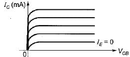
The output characteristic of a CB transistor configuration is shown in figure below.

It is clear that for a constant value of IE, IC is independent of VCB and the curves are parallel to the axis of VCB.
Hence, a CB transistor acts as an ideal current source.

1 Crore+ students have signed up on EduRev. Have you? Download the App
Test: BJT Characteristics & Biasing- 2 - Question 3

The input resistance of a common-collector configuration will be of the order of

Test: BJT Characteristics & Biasing- 2 - Question 4

The common collector amplifier is also Known as

Detailed Solution for Test: BJT Characteristics & Biasing- 2 - Question 4

A common collector amplifier is also known as Emitter follower because the output voltage (emitter voltage) will follow the input voltage.

Test: BJT Characteristics & Biasing- 2 - Question 5

Consider the statements associated with various types of transistor configuration of a BJT:
1. In cut-off region, emitter and collector junctions are both reverse biased.
2. In saturation region, emitter junction is forward biased while collector junction can be either forward biased or reverse biased.
3. In active region, the collector junction is biased in the reverse biased and the emitter junction in the forward biased.
4. The phase shift introduced to the input in CC and CE configurations are each zero degree.

Q. Which of the above statements are correct ?

Detailed Solution for Test: BJT Characteristics & Biasing- 2 - Question 5

• In saturation region, both emitter and collector junctions are forward biased.
• The phase shift introduced to the input signal in CC configuration is 0° while in CE configuration is 180°.
Hence, statements 2 and 4 are not correct.

Test: BJT Characteristics & Biasing- 2 - Question 6

In an n-p-n transistor biased in the active region:

Test: BJT Characteristics & Biasing- 2 - Question 7

Assertion (A): An emitter follower is widely used in electronic instruments.
Reason (R): The voltage gain of emitter follower is very high.

Detailed Solution for Test: BJT Characteristics & Biasing- 2 - Question 7

The voltage gain of emitter follower (or common collector configuration) is less than unity i.e. a low value.
Hence, reason is not true.

Test: BJT Characteristics & Biasing- 2 - Question 8

Assertion (A): Common base amplifier has very low input resistance.
Reason (R): Low emitter ac resistance r'e shunts all other resistances.

Test: BJT Characteristics & Biasing- 2 - Question 9

Consider the following statements:
1. In a p-n-p transistor with normal bias, the collector junction is of low resistance.
2. p-n-p and n-p-n transistors can be interchanged with each other.
3. The circuit arrangement of a transistor used as a buffer is CC (Common Collector).
4. In a CE connected transistor, VCE will be equal to VCC when base current is zero.
5. In a transistor, emitter junction breakdown is due to “Zener effect” while collector junction breakdown is due to “Avalanche effect”.

Q. Which of the statements given above are not correct ?

Detailed Solution for Test: BJT Characteristics & Biasing- 2 - Question 9

• For transistor operation, with normal bias, collector junction is reverse biased due to which collector junction is of high resistance.
• p-n-p and n-p-n transistors cannot he interchanged with each other.
• CC configuration has highest input resistance due to which it is used as buffer ampiifier for impedance matching.
• In CE transistor,
VCE = VCC - ICRC
When IB = 0,
IC is also equal to zero so that
VCE = VCC
• Breakdown voltage 
Since emitter is heavily doped while collector is moderately doped, therefore, emitter junction breakdown is due to “Zener effect” while collector junction breakdown is due to “Avalanche effect.”
Thus, statements 1 and 2 are not correct.

Test: BJT Characteristics & Biasing- 2 - Question 10

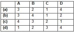
Match List-I with List-II and select the correct answer using the codes given below the lists:
List-I
A. Common emitter Configuration
B. Common collector Configuration
C. Base width modulation
D. Common base Configuration
List-II
1. Early Effect
2. Highest input resistance
3. Inverting amplifier
4. Lowest power gain
Codes:
Test: BJT Characteristics & Biasing- 2 - Question 11

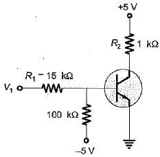
For the transistor shown in the figure below, β = 25. The range of V1 such that, 1.0 < VCE  < 4.5 V is
Detailed Solution for Test: BJT Characteristics & Biasing- 2 - Question 11

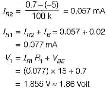
For VCE = 4.5 V,


R1 = 15 kΩ, R2 = 100 kΩ

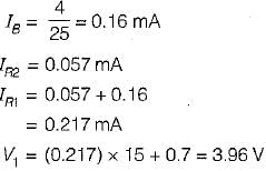
For, VCE = 1.0 V


So, 1.86 < V1 < 3.96 

Test: BJT Characteristics & Biasing- 2 - Question 12

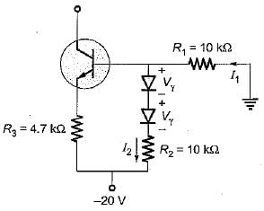
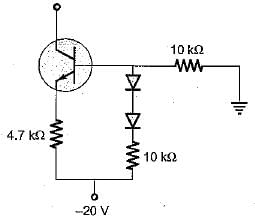
In the bipolar source of figure the diode voltage and transistor VBE voltages are equal. If base current is neglected then collector current is
Detailed Solution for Test: BJT Characteristics & Biasing- 2 - Question 12


Here, 

or,    ..(i)
Applying KVL, we have:
 ..(ii)
Substituting I2 from equation (i) into equation (ii), we get:

Now, 
R1 = R2 = 10 kΩ

or, 
or, 
∴ Collector current, IC = 2.13 mA

Test: BJT Characteristics & Biasing- 2 - Question 13

The Early voltage of a BJT is VA = 75 volt. The minimum required collector current, such that the output resistance is atleast r0 = 200 KΩ is

Detailed Solution for Test: BJT Characteristics & Biasing- 2 - Question 13


or, 

Test: BJT Characteristics & Biasing- 2 - Question 14

The thinnest region in a BJT is_____and the most doped region is________.

Detailed Solution for Test: BJT Characteristics & Biasing- 2 - Question 14

Base is provided with smallest area to reduce transit type or journey time for the majority carriers while travelling from emitter to collector. Emitter is heavily doped to inject its majority carrier into base.

Test: BJT Characteristics & Biasing- 2 - Question 15

In an n-p-n transistor biased in the active region, as the magnitude of the collector-base voltage is increased,

Detailed Solution for Test: BJT Characteristics & Biasing- 2 - Question 15

IC increases because base width reduces due to early effect.

Information about Test: BJT Characteristics & Biasing- 2 Page
In this test you can find the Exam questions for Test: BJT Characteristics & Biasing- 2 solved & explained in the simplest way possible. Besides giving Questions and answers for Test: BJT Characteristics & Biasing- 2, EduRev gives you an ample number of Online tests for practice

Top Courses for Electrical Engineering (EE)

Download as PDF

Top Courses for Electrical Engineering (EE)