Electrical Engineering (EE) Exam  >  Electrical Engineering (EE) Tests  >  Test: First Order RL & RC Circuits- 2 - Electrical Engineering (EE) MCQ

Test: First Order RL & RC Circuits- 2 - Electrical Engineering (EE) MCQ


Test Description

15 Questions MCQ Test - Test: First Order RL & RC Circuits- 2

Test: First Order RL & RC Circuits- 2 for Electrical Engineering (EE) 2024 is part of Electrical Engineering (EE) preparation. The Test: First Order RL & RC Circuits- 2 questions and answers have been prepared according to the Electrical Engineering (EE) exam syllabus.The Test: First Order RL & RC Circuits- 2 MCQs are made for Electrical Engineering (EE) 2024 Exam. Find important definitions, questions, notes, meanings, examples, exercises, MCQs and online tests for Test: First Order RL & RC Circuits- 2 below.
Solutions of Test: First Order RL & RC Circuits- 2 questions in English are available as part of our course for Electrical Engineering (EE) & Test: First Order RL & RC Circuits- 2 solutions in Hindi for Electrical Engineering (EE) course. Download more important topics, notes, lectures and mock test series for Electrical Engineering (EE) Exam by signing up for free. Attempt Test: First Order RL & RC Circuits- 2 | 15 questions in 45 minutes | Mock test for Electrical Engineering (EE) preparation | Free important questions MCQ to study for Electrical Engineering (EE) Exam | Download free PDF with solutions
Test: First Order RL & RC Circuits- 2 - Question 1

Laplace transform analysis gives

Test: First Order RL & RC Circuits- 2 - Question 2

The Laplace transform of the derivative of the signal f(t) = e-t u(t) is

Detailed Solution for Test: First Order RL & RC Circuits- 2 - Question 2

The derivative of function f(t) is
f'(t) = e-tδ (t) + u (t) (-e-t)
= -e-t u(t) + e-tδ(t)

1 Crore+ students have signed up on EduRev. Have you? Download the App
Test: First Order RL & RC Circuits- 2 - Question 3

For a series R - C circuit excited by a dc voltage of 20 V, and with time-constant τ seconds, the voltage across the capacitor at time t = τ is given by

Detailed Solution for Test: First Order RL & RC Circuits- 2 - Question 3

Vc(t) = V(1 - e-t/τ) volts
V = 20 volt (given)
At t = τ, Vc|t = τ = 20 (1 - e-1) volts

Test: First Order RL & RC Circuits- 2 - Question 4

The Laplace-transform equivalent of a given network will have 7/5 F capacitor replaced by 5

Detailed Solution for Test: First Order RL & RC Circuits- 2 - Question 4

Test: First Order RL & RC Circuits- 2 - Question 5

An RC circuit has a capacitor C = 2 μF in series with a resistance R = 1 MΩ The time of 6 secs will be equal to

Detailed Solution for Test: First Order RL & RC Circuits- 2 - Question 5

Time constant of series RC circuit is
τ = RC = 1 x 106 x 2 x 10-6
= 2 secs
Hence, time of 6 seconds will be equal to 3τ = 3 times of time constant.

Test: First Order RL & RC Circuits- 2 - Question 6

The Laplace transform of the gate function shown below is
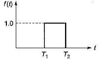
Detailed Solution for Test: First Order RL & RC Circuits- 2 - Question 6

From the given waveform, we have

∴ 

Test: First Order RL & RC Circuits- 2 - Question 7

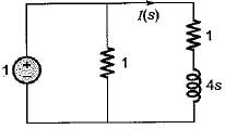
Assuming initial condition to be zero, the current i(t) in the circuit shown below is
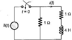
Detailed Solution for Test: First Order RL & RC Circuits- 2 - Question 7

The given circuit in Laplace domain is shown below.

Here 

(Using current divider theorem)

or, i(t) = 0.25 e-0-5t u(t)

Test: First Order RL & RC Circuits- 2 - Question 8

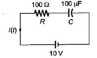
A 10 volts step voltage is applied across a RC series circuit at t = 0 having R = 100 Ω, and C = 100 μF.
The values of i(t) and di(t)/dt at t = 0 are respectively given by

Detailed Solution for Test: First Order RL & RC Circuits- 2 - Question 8


At t = 0, capacitor acts as short-circuit.
So, 

Time constant of given circuit is
τ = RC = 100 x 100 x 10-6
= 10-2 sec = 0.01 sec
With zero initial condition, current in the series RC circuit is


Hence, 
di/dt = -10 e-100t
i(0+) = 0.1 A

Test: First Order RL & RC Circuits- 2 - Question 9

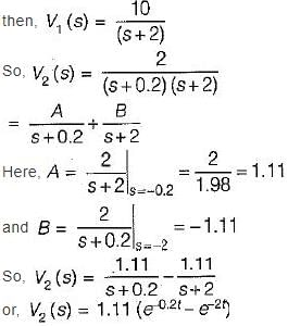
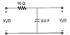
If the input voltage V1(t) = 10 e-2t V then, the output voltage V2(t) for the circuit shown below is
Detailed Solution for Test: First Order RL & RC Circuits- 2 - Question 9

Given circuit is a low-pass filter having transfer function


When, V1(t) = 10e-2t

Test: First Order RL & RC Circuits- 2 - Question 10

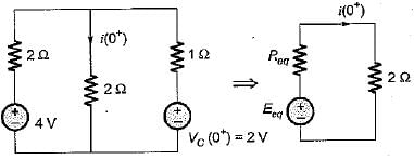
In the circuit shown below, the switch 'S' is opened at t = 0. Prior to that, switch was closed.
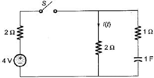
The current i(t) is at t = 0+ is

Detailed Solution for Test: First Order RL & RC Circuits- 2 - Question 10

For t = 0-, switch Sis closed. Hence, in steady state capacitor will act as open circuit.
Thus, V0(0-) = VC(0+) = 2 volts
The circuit at t = 0+ is shown below where,
cananitor ants as a constant voltage source.

Using source transformation,

and 

Hence, 

Test: First Order RL & RC Circuits- 2 - Question 11

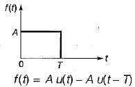
A rectangular pulse of duration T and magnitude A has the Laplace transform

Detailed Solution for Test: First Order RL & RC Circuits- 2 - Question 11


∴ 

Test: First Order RL & RC Circuits- 2 - Question 12

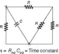
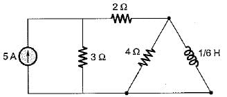
The time constant of the circuit shown below is
Detailed Solution for Test: First Order RL & RC Circuits- 2 - Question 12

Reg across inductor 

(5 A C.S open circuited)
∴ Time constant of RL circuit is

Test: First Order RL & RC Circuits- 2 - Question 13

Assertion (A): Laplace transform is preferred for solving networks involving higher order differential equations.
Reason (R): The classical method for solving differential equations of higher order is quite cumbersome.

Test: First Order RL & RC Circuits- 2 - Question 14

Assertion (A): In a purely capacitive circuit, the current wave is more distorted than the voltage wave.
Reason (R): The harmonics in the current wave are increased in proportion to their frequency numbers.

Test: First Order RL & RC Circuits- 2 - Question 15

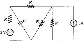
The time constant of the circuit shown below is
Detailed Solution for Test: First Order RL & RC Circuits- 2 - Question 15

For finding time constant of the circuit 5 A current source is open circuited and 2 V voltage source is short circuited.


Ceq = C
∴ 

Information about Test: First Order RL & RC Circuits- 2 Page
In this test you can find the Exam questions for Test: First Order RL & RC Circuits- 2 solved & explained in the simplest way possible. Besides giving Questions and answers for Test: First Order RL & RC Circuits- 2, EduRev gives you an ample number of Online tests for practice

Top Courses for Electrical Engineering (EE)

Download as PDF

Top Courses for Electrical Engineering (EE)