Test: Velocity & Acceleration Analysis - 3 - Mechanical Engineering MCQ
10 Questions MCQ Test - Test: Velocity & Acceleration Analysis - 3
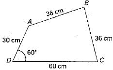
Consider a four-bar mechanism shown in the given figure. The driving link DA is rotation uniformly at a speed of 100 rpm clockwise
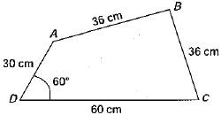
Q. The velocity of A will be

Q. The velocity of A will be
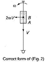
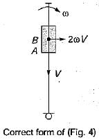
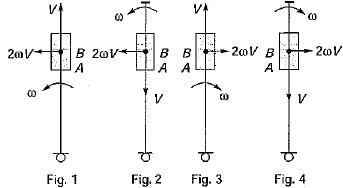
The directions of Coriolis component of acceleration, 2 ωV, of the slider A with respect to the coincident point B is shown in figure 1,2, 3 and 4. Directions shown by figures

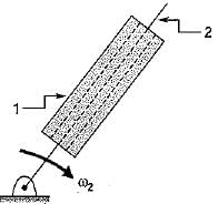
In the figure shown, the relative velocity of link 1 with respect of link 2 is 12 m/sec. Link 2 rotates at a constant speed of 120 rpm. The magnitude of Coriolis component of acceleration of link 1 is

The number of links in a planer mechanism with revolute joints having 10 instantaneous centre is
The figure below shows a planer mechanism with single degree of freedom. The instant center 24 for the given configuration in located at a position
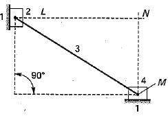
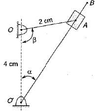
Figure shows a quick return mechanism. The crank OA rotates clockwise uniformly.
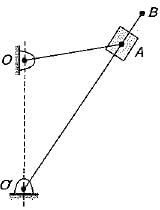
OA = 2 cm; OO' = 4 cm
Q. The ratio of time for forward motion to that for return motion is
A slider sliding at 10 cm/s on a link which is rotating at 60 rpm is subjected to Coriolis acceleration of magnitude
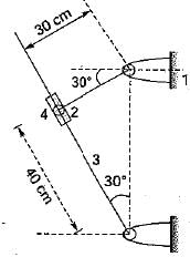
In the figure given the link 2 rotates at an angular velocity of 2 rad/s. What is the magnitude of Coriolis acceleration experienced by the link 4?
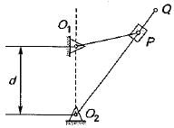
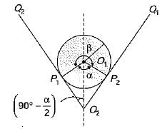
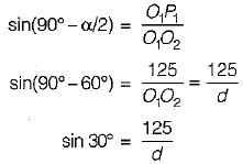
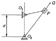
A simple quick return mechanism is shown in the figure. The forward to return ratio of the quick return mechanism is 2 : 1. If the radius of the crank O1P is 125 mm, then the distance ‘of’ (in mm) between the crank centre to lever pivot centre point should be
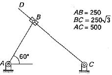
For the configuration shown, the angular velocity of link AB is 10 rad/s counter clockwise. The magnitude of the relative sliding velocity (in ms-1) of slider B with respect to rigid link CD is
