Test: State Variable Analysis- 2 - Electronics and Communication Engineering (ECE) MCQ
10 Questions MCQ Test - Test: State Variable Analysis- 2

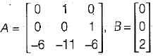
The state variable description of an autonomous system is, X = AX where X is a two-dimensional vector and A is a matrix given by

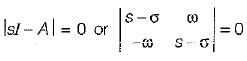
The eigen values of A are
The eigen values of A are
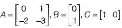
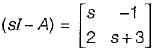
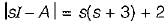
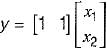
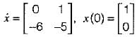
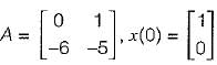
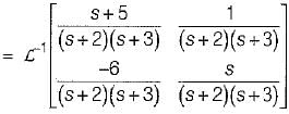
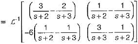
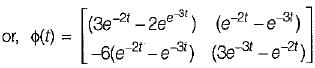
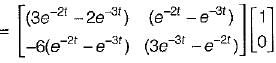
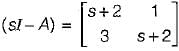
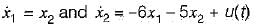
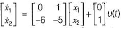
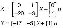
The system equations are given by
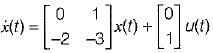
y(t) = [1 0]x(t)
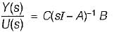
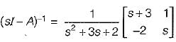
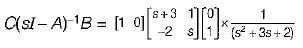
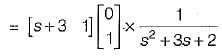
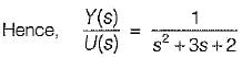
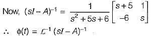
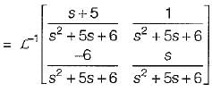
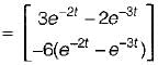
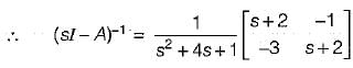
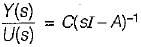
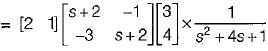
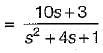
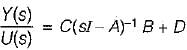
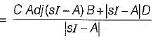
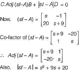
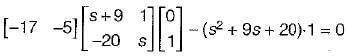
The transfer function of the above system is
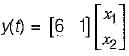
y(t) = [1 0]x(t)
The transfer function of the above system is


Consider the following statements related to state space analysis of control systems:
1. The zeros of the system can be obtained from eigen value of the system matrix.
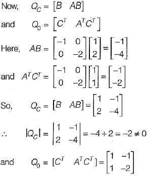
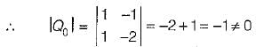
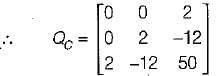
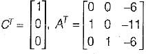
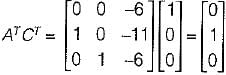
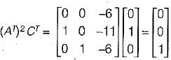
2. A system is said to be observable if every state x0 can be exactly determined from the measurement of the output ‘y’ over a finite interval of time 0 ≤ t ≤ tf.
3. The process by which transfer function changes to state diagram or state equations is called decomposition of the transfer function.
4. The state space techniques can be applied to linear and time invariant systems only.
Which of the above statements are correct?
1. The zeros of the system can be obtained from eigen value of the system matrix.
2. A system is said to be observable if every state x0 can be exactly determined from the measurement of the output ‘y’ over a finite interval of time 0 ≤ t ≤ tf.
3. The process by which transfer function changes to state diagram or state equations is called decomposition of the transfer function.
4. The state space techniques can be applied to linear and time invariant systems only.
Consider the system shown in figure below:
The system is
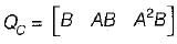
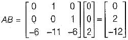
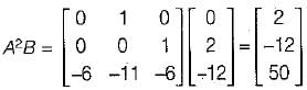
The transfer function of the system shown below is
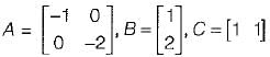
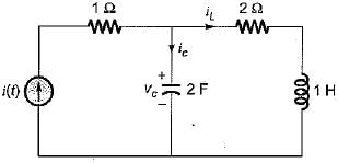
The state equation for the circuit shown below is
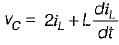
 .............(1)
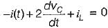
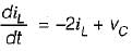
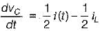 ..........(2)
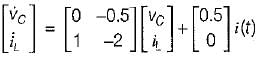
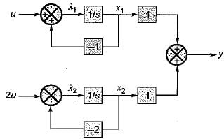
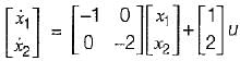
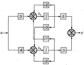
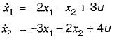
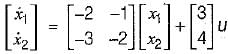
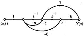
The state space representation of the system represented by the SFG shown below is
The state variable representation of a system is given by:
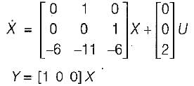
The system is


Important Questions for State Variable Analysis- 2
State Variable Analysis- 2 MCQs with Answers
Online Tests for State Variable Analysis- 2
|
© EduRev
|
Education Revolution
|


|


