Test: Slope & Deflection Level - 3 - Mechanical Engineering MCQ
15 Questions MCQ Test - Test: Slope & Deflection Level - 3
A simply supported beam of span 6 m carries two concentrated loads of 2N each at 1 m distance from each of the supports. If the flexural rigidity of the beam is constant. the slope at the support is
A prismatic beam of length L is simply supported at its ends and subjected to a total UDL of W spread over its entire span. It is then propped at its Centre to neutralize the deflection. The net B.M. at its Centre will be
A cantilever beam of uniform EI has a span equal to ‘L’. An upward force W acts at the midpoint of the beam and a downward force P acts at the free end. In order that the deflection at the free end is zero, the relation between P and W should be
A point load ‘W’ is acting at the mid-span of a cantilever of length ‘L’. If the free end is supported on a rigid prop, the reaction of the prop is
A cantilever AB, 3 m long carries a uniformly distributed load of 2 kN/m throughout its length, rests over a similar cantilever of same cross-section and same material, 2 m long and shown below. What is reaction C?

A beam ABC of length 3L has one support at the left end and the other support at a distance 2L from the left end. The beam carries a point load W at the right end. The deflection at the right end is
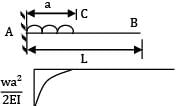
A cantilever of Length ‘L’ carries a uniformly distributed load of w per unit run for a distance ‘a’ from the fixed end. The deflection at free end is
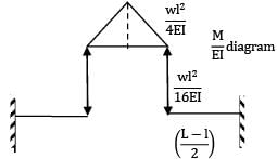
A uniform beam of length ‘L’ is simply and symmetrically supported to a span ‘l’ find the ratio L/l so that the upward deflection at each end equals the downward deflection at mid span, due to a concentrated point load at mid span.
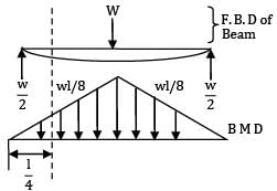
A prismatic simply supported beam carries a point load at mid-span section due to which a slope of 2° is produced at support sections. The slope at quarter span sections is
A beam of span 6m and of uniform flexural rigidity EI = 40000 kNm2 is subjected to a clockwise couple of 300 kNm at a distance of 4m from the left end. The deflection at the point of application of the couple is _______ mm

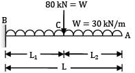
A cantilever 3m long, and of symmetrical section 250 mm deep carries a uniformly distributed load of 30 kN/m run throughout together with a point of 80 kN at a section 1.2 m from fixed end. The deflection at the free end is __________ mm (Take E = 200 GPa, I = 54000 cm4)
A cantilever of length 6 m is loaded as shown in the figure below. The maximum deflection in the beam is
E = 200 MPa, I = 1 × 10⁻⁴ m−4, W = 1 kN.
P1 = 3W P2 = 2W P3 = 1W

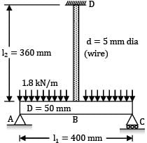
A horizontal steel rod ABC of diameter 50 mm and length 400 mm carrying a uniformly distributed load of 1.8 kN/m is simply supported at its ends A and C and is also supported at its mid-point B by its connection to a hanging vertical steel wire of 5 mm diameter and length 360 mm as shown in figure below. The deflection at point B is _________ mm (Take E = 2 × 10⁵ N/mm2).
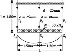
A horizontal beam (I = 8.616 × 107mm4) carries a uniformly distributed load of 50 kN over its length of 3m. The beam is supported by three vertical steel tie rods, each 1.80m long. One at each end and one at in the middle, the end rods having a diameter of 25mm and the centre rod a diameter of 30mm. The deflection of the centre of the beam is _________mm (Take E = 2 × 10⁵ N/mm2)
(Take E = 2 × 10⁵ N/mm2)
determine the slope and deflection at a point in a beam is suitable for beams subjected to concentrated loads and can be extended to uniformly distributed loads Reason(R): Macaulay’s method is based upon the modification of moment of area method. This is applicable to a simple beam carrying a single concentrated load but by superposition, this method can be extended to cover any kind of loading.


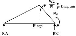
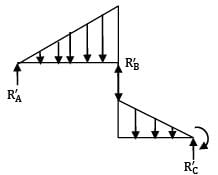







 = 306796.875 mm
 = 19.635 mm2
 = 86.228 N
 = 0.0079 mm
 = 490.87 mm2
 = 706.86 mm2


