GATE Exam  >  GATE Tests  >  Test: Basic Electrical Components - GATE MCQ

Test: Basic Electrical Components - GATE MCQ


Test Description

15 Questions MCQ Test - Test: Basic Electrical Components

Test: Basic Electrical Components for GATE 2024 is part of GATE preparation. The Test: Basic Electrical Components questions and answers have been prepared according to the GATE exam syllabus.The Test: Basic Electrical Components MCQs are made for GATE 2024 Exam. Find important definitions, questions, notes, meanings, examples, exercises, MCQs and online tests for Test: Basic Electrical Components below.
Solutions of Test: Basic Electrical Components questions in English are available as part of our course for GATE & Test: Basic Electrical Components solutions in Hindi for GATE course. Download more important topics, notes, lectures and mock test series for GATE Exam by signing up for free. Attempt Test: Basic Electrical Components | 15 questions in 20 minutes | Mock test for GATE preparation | Free important questions MCQ to study for GATE Exam | Download free PDF with solutions
Test: Basic Electrical Components - Question 1

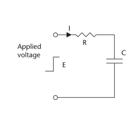
What is the voltage across the capacitor in the given figure 35s after the input voltage

steps from 0V to 54V, if the value of the resistor is 47 kΩ and the capacitor is 1.5F?
Detailed Solution for Test: Basic Electrical Components - Question 1
Ec = 54(1 − e−35 × 1000000/1000 × 47 × 1000 × 1.5)V = 54 (1 − 1/e0.5)V

Ec = 54(1 − 0.606) = 21.3V

In an RC network when a step voltage is applied, the voltage across the capacitor is given by the equation

Ec = E{1− e-(t/RC)}

where Ec is the voltage across the capacitor at any instant of time, E is the source

voltage, t is the time (seconds) after the step is applied, R is in ohms and C is in farads.

Test: Basic Electrical Components - Question 2

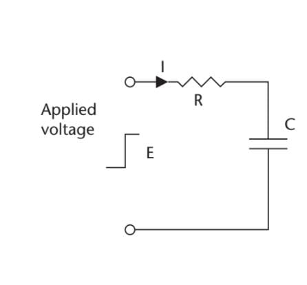
What is the time constant for the circuit shown in the given figure, if the resistor has a

value of 220 kΩ, and the capacitor is 2.2 F?
Detailed Solution for Test: Basic Electrical Components - Question 2
t = 2.2 × 10−6 × 220 × 103 sec = 484 × 10−3 sec = 0.484 sec

The time constant of the voltage in a capacitive circuit is defined as:

t = CR

where t is the time (seconds) it takes for the voltage to reach 63.2% of its final or

aiming voltage after the application of an input voltage step (charging or discharging).

1 Crore+ students have signed up on EduRev. Have you? Download the App
Test: Basic Electrical Components - Question 3

The resistive elements in a strain gauge are each 5kΩ. A digital voltmeter with ranges of 10V, 1V, and 0.1V, and a resolution of 0.1% of FSD, is used to measure the output voltage. If R2 is the fixed element and R1 is the element measuring strain, what is the minimum change in R1 that can be detected? Assume a supply of 10V.

Detailed Solution for Test: Basic Electrical Components - Question 3
To measure the output voltage ≈ 5V, the 10V range is required, giving a resolution or sensitivity of 10 mV.

VR = 5.01V = 5,000 × 10/(R1 + 5,000)V

5.01(R1 + 5,000) = 50,000

R1 = (50,000/5.01) − 5,000 = 4,980Ω

Resolution = 5,000 − 4,980 = 20Ω

Test: Basic Electrical Components - Question 4

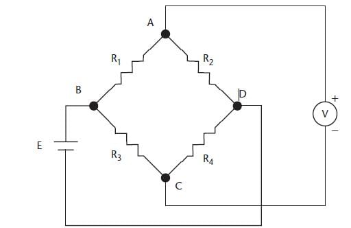
Resistors R1 and R2 in the bridge circuit shown in the given figure are the strain gauge elements of 5kΩ each. Resistors R3 and R4 are fixed resistors, with values of 4.3 kW. A digital voltmeter with ranges of 10V, 1V, and 0.1V, and a resolution of 0.1% of FSD, is used to measure the output voltage. What is the minimum change in R1 that can be detected by the meter? Assume the supply E is 10V.
Detailed Solution for Test: Basic Electrical Components - Question 4
The voltage at point C will be 5.0V, because R3 = R4, and the voltage at C equals one-half of the supply voltage. The voltmeter can use the 0.1V range, because the offset is 0V, giving a resolution of 0.1 mV. The voltage that can be sensed at A is given by

EAD = 10 × R2/(R1 + R2) = 5.00 + 0.0001V

R1 = (50,000/50,001) − 5,000Ω

R1 = −49,999

Resolution = 1Ω

Test: Basic Electrical Components - Question 5

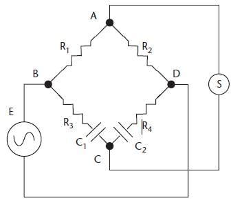
If the bridge circuit in the given figure is balanced, with R1 = 15 kΩ, R2 = 27 kΩ, R3= 18 kΩ, and C1 = 220 pF, what are the values of R4 and C2?
Detailed Solution for Test: Basic Electrical Components - Question 5
R2R3 = R1R4

R4 = 27 × 18/15 = 32.4 kΩ

Additionally,

C2R2 = C1R1

C2 = 220 × 15/27 = 122 pF

Test: Basic Electrical Components - Question 6

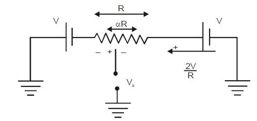
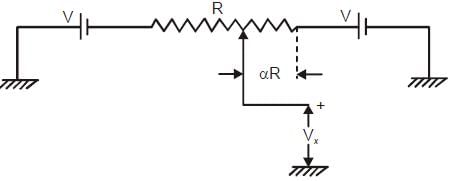
In the potentiometer circuit shown in the figure, the expression for Vx is
Detailed Solution for Test: Basic Electrical Components - Question 6

Using KVL,

Vx + (αR) 2V/R - V = 0

Test: Basic Electrical Components - Question 7

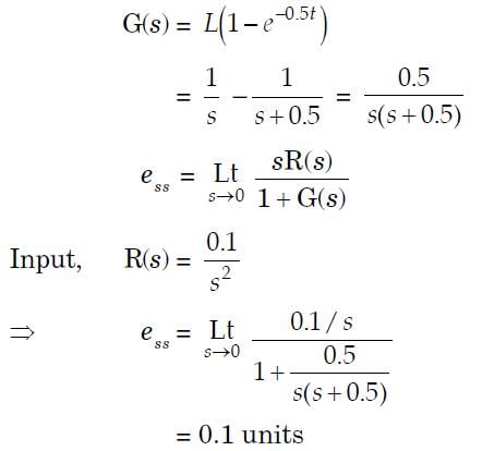
The response of a first-order measurement system to a unit step input is 1 – e– 0.5t, where t is in seconds. A ramp of 0.1 units per second is given as the input to this system. The error in the measured value after transients have died down is

Detailed Solution for Test: Basic Electrical Components - Question 7

Test: Basic Electrical Components - Question 8

A metal wire has a uniform cross-section A, length, and resistance R between its two endpoints. It is uniformly stretched so that its length becomes l. The new resistance is

Detailed Solution for Test: Basic Electrical Components - Question 8

Volume is constant

lA = l’A’

lA = α l A’

A’ = A/α

R’ = ρl'/A' = ρ αlα/A = α2 R

Test: Basic Electrical Components - Question 9

A variable air gap type capacitor consists of two parallel plates: a fixed plate and a moving plate at a distance x. If a potential V is applied across the two plates, then the force of attraction between the plates is related to x as

Detailed Solution for Test: Basic Electrical Components - Question 9

E = ½ CV2. = ½  εA/x V2

F = -δEX = ½  εA/xx V2 which is inversely proportional to x2

Test: Basic Electrical Components - Question 10

The expression for the capacitance (C in pF) of a parallel plate capacitor is given by:

C = 6.94 × 10– 3 (d2/S). The diameter (d) of each plate is 20 mm and the spacing between the plates

(S) is 0.25 mm. The displacement sensitivity of the capacitor is approximate:

Detailed Solution for Test: Basic Electrical Components - Question 10

C = 6.94 x 10- 3 (d2/S) PF

Displacement sensitivity = dC/dS = -6.94 x 10 - 3 x 20 2 / (0.25)2 = - 44.4 pF/mm

Test: Basic Electrical Components - Question 11

Which of the following can be measured using a Wheatstone bridge?

Detailed Solution for Test: Basic Electrical Components - Question 11
Wheatstone bridge cannot be limited to measurement of a single quantity only, it can be used to measure resistance, capacitance, impedance, inductance etc. with some modifications.
Test: Basic Electrical Components - Question 12

Accuracy in a bridge measurement depends on

Detailed Solution for Test: Basic Electrical Components - Question 12
Both sensitivity of indicator and applied voltage affects the accuracy in bridge measurement.
Test: Basic Electrical Components - Question 13

In a Wheatstone bridge, which of the following is used as a null detector?

Detailed Solution for Test: Basic Electrical Components - Question 13
Null detector is used to indicate zero current flow, and the device used is a galvanometer.
Test: Basic Electrical Components - Question 14

Which of the following statements is correct for impedance?

Detailed Solution for Test: Basic Electrical Components - Question 14
Impedance of pure resistance is purely real and for an inductor purely imaginary, where the inductor is a reactive component.
Test: Basic Electrical Components - Question 15

What is the purpose of Owens Bridge?

Detailed Solution for Test: Basic Electrical Components - Question 15
Owens Bridge is an AC bridge that is used to measure reactance.
Information about Test: Basic Electrical Components Page
In this test you can find the Exam questions for Test: Basic Electrical Components solved & explained in the simplest way possible. Besides giving Questions and answers for Test: Basic Electrical Components, EduRev gives you an ample number of Online tests for practice
Download as PDF