GATE Exam  >  GATE Tests  >  Test: Transducers- 1 - GATE MCQ

Test: Transducers- 1 - GATE MCQ


Test Description

25 Questions MCQ Test - Test: Transducers- 1

Test: Transducers- 1 for GATE 2024 is part of GATE preparation. The Test: Transducers- 1 questions and answers have been prepared according to the GATE exam syllabus.The Test: Transducers- 1 MCQs are made for GATE 2024 Exam. Find important definitions, questions, notes, meanings, examples, exercises, MCQs and online tests for Test: Transducers- 1 below.
Solutions of Test: Transducers- 1 questions in English are available as part of our course for GATE & Test: Transducers- 1 solutions in Hindi for GATE course. Download more important topics, notes, lectures and mock test series for GATE Exam by signing up for free. Attempt Test: Transducers- 1 | 25 questions in 30 minutes | Mock test for GATE preparation | Free important questions MCQ to study for GATE Exam | Download free PDF with solutions
Test: Transducers- 1 - Question 1

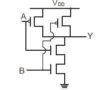
The given circuit represents ______

Detailed Solution for Test: Transducers- 1 - Question 1
The given circuit represents the NAND gate.
Test: Transducers- 1 - Question 2

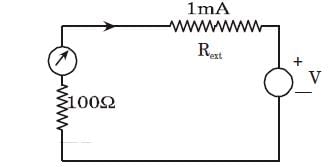
A galvanometer with internal resistance 100 and full-scale current 1 mA is used to realize a dc voltmeter with a full-scale range of 1V. The full-scale range of this voltmeter can be extended to 10V by connecting an external resistance of value

Detailed Solution for Test: Transducers- 1 - Question 2

V = 10 = (100 + Rext ) 10– 3

Rext = 9.9 k

1 Crore+ students have signed up on EduRev. Have you? Download the App
Test: Transducers- 1 - Question 3

A piezoelectric type accelerometer has a sensitivity of 100 mV/g. The transducer is subjected to a constant acceleration of 5g. The steady-state output of the transducer will be

Detailed Solution for Test: Transducers- 1 - Question 3
Steady state output = sensitivity acceleration

= 100 mV/g 5g

= 0.5 V.

Test: Transducers- 1 - Question 4

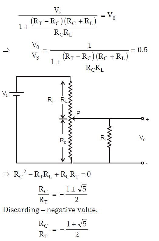
The figure shows a potentiometer of total resistance RT with a sliding contact.
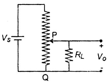
The resistance between the points P and Q of the potentiometer at the position of the contact shown is RC, and the voltage ratio Vo/Vs at this point is 0.5. If the ratio RL/RT = 1, the ratio RC/RT is

Detailed Solution for Test: Transducers- 1 - Question 4

Test: Transducers- 1 - Question 5

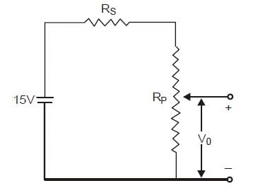
A 4 kΩ, 0.02 W potentiometer is used in the circuit shown below. The minimum value of the

resistance Rs to protect the potentiometer is
Detailed Solution for Test: Transducers- 1 - Question 5

0.02 = I2 x 4 x 103

⇒ I = 2.23 mA

and I ( RS + RP ) = 15 ⇒ Rs + RP = 6.71 kΩ

⇒ RS = 2.71 kΩ

Test: Transducers- 1 - Question 6

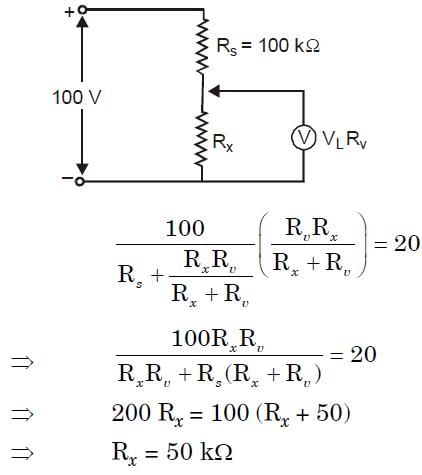
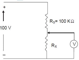
The voltmeter is shown in the following figure has a sensitivity of 500Ω /V and a full scale of 100 V. When connected in the circuit as shown, then the meter reads 20 V. The value of Rx is
Detailed Solution for Test: Transducers- 1 - Question 6

Test: Transducers- 1 - Question 7

A quartz piezo-electric type pressure sensor has a built-in charge amplifier. The sensor has a sensitivity of 1 μV/Pa. It is subjected to a constant pressure of 120 kPa. The output of the transducer at a steady state is

Detailed Solution for Test: Transducers- 1 - Question 7

Output voltage = Sensitivity × pressure

= 1 μv/Pa × 120 kPa

= 120 mV

Test: Transducers- 1 - Question 8

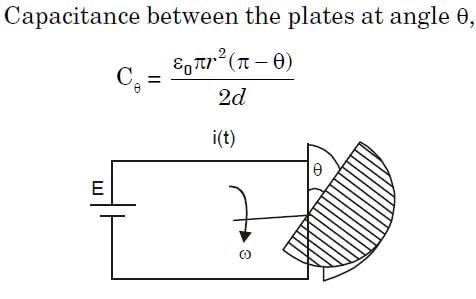
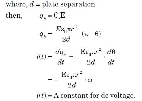
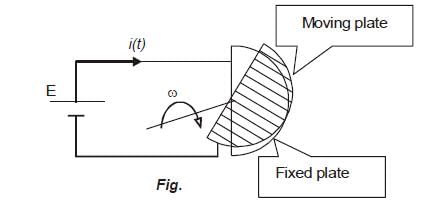
A variable capacitance angular velocity pickup is made with two concentrically mounted parallel semi-circular plates with a small separation between them, as shown in Figure. A dc voltage is connected across the terminals of the capacitance sensor, as shown. For a constant angular velocity, the waveform of the current i (t) will be
Detailed Solution for Test: Transducers- 1 - Question 8

Test: Transducers- 1 - Question 9

A strain gauge of resistance 120 and gauge factor 2.0 is at zero strain condition A 200 kΩ

fixed resistance is connected in parallel with it. Then the combination will represent an equivalent

strain of

Detailed Solution for Test: Transducers- 1 - Question 9

Gauge Factor, Gf

2 = =  = -300 μm/m

Negative Sign shows compressive strain.

Test: Transducers- 1 - Question 10

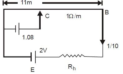
A wire potentiometer of length 11 m and resistance 1 /m balances a standard cell voltage of 1.018 V at a length of 10 m 18 cm. If the voltage of the battery supplying the current through the potentiometer is 2.0 V, then the value of the series resistance connected to the potentiometer is

Detailed Solution for Test: Transducers- 1 - Question 10

Current in AC: 1.081/10.18 = 0.1 A

Voltage across AB = 0.1 x 11 = 1.1V

Voltage across Rh = 2 - 1.1 = 0.9 V

Then, Rh = 0.9/0.1 = 9 Ω

Test: Transducers- 1 - Question 11

An N-type semiconductor or strain gauge has a nominal resistance of 1000Ω and a gauge factor of 100. The resistance of the gauge, when a compressive strain of 100mm/m is applied, is

Detailed Solution for Test: Transducers- 1 - Question 11

Gauge Factor, Gf

ΔR/R = - 100 x 100 x 10-6

ΔR = -10Ω

then, resistance of the gauge = 1000 – 10

= 990Ω

Test: Transducers- 1 - Question 12

A quartz crystal (Young’s modulus, E = 9 × 10¹⁰ N/m2) with piezo-electric properties has a diameter of 10 mm and thickness of 2 mm. Its voltage sensitivity constant is 4500 V/m. If the voltage output is 127.3 V, the applied load is approximately

Detailed Solution for Test: Transducers- 1 - Question 12

E = 9 × 10¹⁰ N/m2

g = voltage sensitivity = 4500 V/m

= (4500 x 106)/E V-mN-1

V = voltage output = 127.3 V

We know that , V = g.t.

where t = thickness

F = applied load,

A = Area

Substituting the values of all the given parameters in the above relations and get the value of F.

F= 99.98N ~ 100 N

Test: Transducers- 1 - Question 13

A strain gauge is attached to a bar of length 20 cm, which is subjected to a tensile force. The nominal resistance of the strain gauge is 100 Ω . The changes in resistance and elongation in the bar measured are 0.35Ω and 0.2 mm, respectively. The gauge factor of the strain gauge is

Detailed Solution for Test: Transducers- 1 - Question 13

Gauge Factor, Gf

Substituting the values, we get

Gauge factor= 3.5

Test: Transducers- 1 - Question 14

Amount of heat liberated or absorbed when 1A current passes is called ____________

Detailed Solution for Test: Transducers- 1 - Question 14
Peltier coefficient relates heat liberated or absorbed and current flow.
Test: Transducers- 1 - Question 15

Total Seebeck effect can be found as _____________

Detailed Solution for Test: Transducers- 1 - Question 15
All three effects, Peltier, Seebeck, and Thomson effects, are connected, and the total Seebeck effect can be found as partly Peltier and partly Thomson effect.
Test: Transducers- 1 - Question 16

Hall Effect is a/an _____________

Detailed Solution for Test: Transducers- 1 - Question 16
Hall Effect is due to the interaction of the magnetic field and moving electric charge, which results in the development of forces that alter the motion of charge.
Test: Transducers- 1 - Question 17

At equilibrium Lorentz forces will be ____________ of the Hall Effect force.

Detailed Solution for Test: Transducers- 1 - Question 17
At equilibrium condition, Lorentz force and Hall Effect force balances each other, and they will be equal in magnitude.
Test: Transducers- 1 - Question 18

Which of the following represents the correct expression of Lorentz force?

Detailed Solution for Test: Transducers- 1 - Question 18
The magnitude of Lorentz force will be equal to the ratio of the product of electric charge and Hall potential with width in meters.
Test: Transducers- 1 - Question 19

Hall potential is inversely proportional to magnetic flux density.

Detailed Solution for Test: Transducers- 1 - Question 19
Hall potential is always directly proportional to magnetic flux density. Expression is given as EH=BbV, where b is the width and V represents the velocity.
Test: Transducers- 1 - Question 20

Hall Effect is clearly visible in _______________

Detailed Solution for Test: Transducers- 1 - Question 20
Hall coefficient depends on the number of free charge carriers, and it is visible in semiconductors.
Test: Transducers- 1 - Question 21

Force exerted by magnetic field in Hall Effect transducers is ____________

Detailed Solution for Test: Transducers- 1 - Question 21
Lorentz force is the force exerted by a magnetic field in Hall Effect transducers. On equilibrium condition, Lorentz force balances Hall Effect force.
Test: Transducers- 1 - Question 22

Which of the following represents the correct expression for Lorentz force?

Detailed Solution for Test: Transducers- 1 - Question 22
Lorentz force is the magnetic flux density, electronic charge, and velocity of the charge.
Test: Transducers- 1 - Question 23

Which of the following represents the output of the Hall Effect transducer?

Detailed Solution for Test: Transducers- 1 - Question 23
Output of Hall Effect transducer is called Hall potential and is denoted by EH.
Test: Transducers- 1 - Question 24

Hall Effect transducer can be used to measure ___________

Detailed Solution for Test: Transducers- 1 - Question 24

A time delay of 10-14 is required for a Hall Effect transducer to attain equilibrium.

Test: Transducers- 1 - Question 25

Hall Effect transducer can be used to measure ___________

Detailed Solution for Test: Transducers- 1 - Question 25

Hall Effect transducers can measure linear and angular displacement and magnetic field etc.

Information about Test: Transducers- 1 Page
In this test you can find the Exam questions for Test: Transducers- 1 solved & explained in the simplest way possible. Besides giving Questions and answers for Test: Transducers- 1, EduRev gives you an ample number of Online tests for practice
Download as PDF