GATE Exam  >  GATE Tests  >  Test: Sensor & Industrial Instrumentation- 2 - GATE MCQ

Test: Sensor & Industrial Instrumentation- 2 - GATE MCQ


Test Description

25 Questions MCQ Test - Test: Sensor & Industrial Instrumentation- 2

Test: Sensor & Industrial Instrumentation- 2 for GATE 2025 is part of GATE preparation. The Test: Sensor & Industrial Instrumentation- 2 questions and answers have been prepared according to the GATE exam syllabus.The Test: Sensor & Industrial Instrumentation- 2 MCQs are made for GATE 2025 Exam. Find important definitions, questions, notes, meanings, examples, exercises, MCQs and online tests for Test: Sensor & Industrial Instrumentation- 2 below.
Solutions of Test: Sensor & Industrial Instrumentation- 2 questions in English are available as part of our course for GATE & Test: Sensor & Industrial Instrumentation- 2 solutions in Hindi for GATE course. Download more important topics, notes, lectures and mock test series for GATE Exam by signing up for free. Attempt Test: Sensor & Industrial Instrumentation- 2 | 25 questions in 30 minutes | Mock test for GATE preparation | Free important questions MCQ to study for GATE Exam | Download free PDF with solutions
Test: Sensor & Industrial Instrumentation- 2 - Question 1

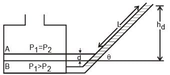
A well of cross-sectional area aw is connected to an inclined tube of cross-sectional area to form a differential pressure gauge as shown in the figure below. When p1 = p2 the common liquid level is denoted by A. When p1 > p2, the liquid level in the well is depressed to B, and the level in the tube rises by l along its length such that the difference in the tube and well levels is hd. (2007)
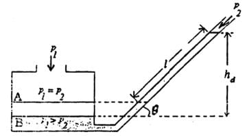
The angle of inclination θ of the tube with the horizontal is

Detailed Solution for Test: Sensor & Industrial Instrumentation- 2 - Question 1

The volume of displaced liquid would be the same

=>

The pressure exerted by the displaced liquid in both columns will be the .literssame, therefore

=>

Test: Sensor & Industrial Instrumentation- 2 - Question 2

The accompanying figure shows a VERTICAL venturi meter with upward water flow. When the measured static pressure difference, p1 - p2, between the inlet and the throat is 30 kPa, the flow rate is found to be 50 litres per second. Assume that the coefficient of discharge remains the same. (2007)
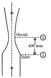
When p1 - p2 = 20 kPa, the flow rate, in litres per second, is

Detailed Solution for Test: Sensor & Industrial Instrumentation- 2 - Question 2
Flow rate,

Where f = density of the liquid.

=>

Test: Sensor & Industrial Instrumentation- 2 - Question 3

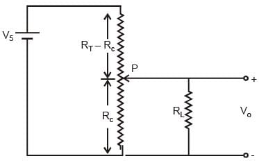
The figure shows a potentiometer of total resistance RT with a sliding contact.
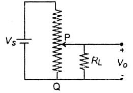
The resistance between the points P and Q of the potentiometer at the position of the contact shown is RC, and the voltage ratio VO / VS at this point is 0.5. If the ratio RL / RT = 1, the ratio RC / RT is (2007)

Detailed Solution for Test: Sensor & Industrial Instrumentation- 2 - Question 3

Discarding - negative value,

Test: Sensor & Industrial Instrumentation- 2 - Question 4

A 4 kΩ, 0.02 W potentiometer is used in the circuit shown below. The minimum value of the resistance Rs to protect the potentiometer is (2006)
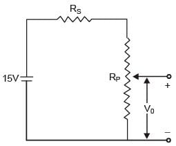
Detailed Solution for Test: Sensor & Industrial Instrumentation- 2 - Question 4
0.02 = I2 x 4 x 103

and

⇒ Rs + Rp = 6.71 kΩ

⇒ Rs = 2.71 kΩ

Test: Sensor & Industrial Instrumentation- 2 - Question 5

A type J (iron-constantan) thermocouple has a voltage sensitivity of 55 V/°C

A digital voltmeter (DVM) is used to measure the voltage under the condition shown in the following figure. (2006)
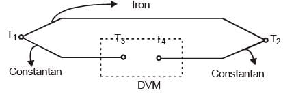
Given that T1 = 3000C, T2 = 1000C and T3 = T4 = 200 C, the meter will indicate a voltage of

Detailed Solution for Test: Sensor & Industrial Instrumentation- 2 - Question 5
Indicated voltage,

V = S. ΔT

= S. (T1 - T2)

= (55 V/0C) x 200 = 11 mV.

Test: Sensor & Industrial Instrumentation- 2 - Question 6

A metal wire has a uniform cross-section A, length l, and resistance R between its two endpoints. It is uniformly stretched so that its length becomes α l. The new resistance is (2006)

Detailed Solution for Test: Sensor & Industrial Instrumentation- 2 - Question 6
Volume is constant

lA = l' A'

lA = αl. A

=> A' = A / α

Test: Sensor & Industrial Instrumentation- 2 - Question 7

The secondary induced voltages of an LVDT, shown in the following figure, at the null position are respectively. Then the null voltage of the LVDT is (2006)
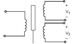
Detailed Solution for Test: Sensor & Industrial Instrumentation- 2 - Question 7
Null voltage,

Δv0 = Iv1 - v2I

= I1 - cos 10° - i sin 10°I

= I0.02I + I0.17I

= 0.174 volts.

Test: Sensor & Industrial Instrumentation- 2 - Question 8

A variable air gap type capacitor consists of two parallel plates: a fixed plate and a moving plate at a distance x. If a potential V is applied across the two plates, then the force of attraction between the plates is related to x as (2006)

Detailed Solution for Test: Sensor & Industrial Instrumentation- 2 - Question 8

Test: Sensor & Industrial Instrumentation- 2 - Question 9

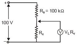
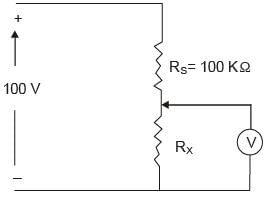
The voltmeter is shown in the following figure has a sensitivity of 500 Ω/V and a full scale of 100 V. When connected in the circuit as shown, then the meter reads 20 V.

The value of Rx is (2006)
Detailed Solution for Test: Sensor & Industrial Instrumentation- 2 - Question 9

=>

=> 200 Rx = 100 (Rx + 50)

=> Rx = 50 kΩ

Test: Sensor & Industrial Instrumentation- 2 - Question 10

In the circuit shown below, the current through the PMMC meter is assumed to be zero.

The ideal switch toggles between position 1 and position 2. For each position, it is connected for time T / 2. Assume R4 CX < t="" 2="" and="" />2 CX >> T / 2. (2006)
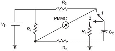
Q. The capacitor CX can be charged up to the maximum voltage

Detailed Solution for Test: Sensor & Industrial Instrumentation- 2 - Question 10

Test: Sensor & Industrial Instrumentation- 2 - Question 11

In the circuit shown below, the current through the PMMC meter is assumed to be zero.

The ideal switch toggles between position 1 and position 2. For each position, it is connected for time T / 2. Assume R4 CX < t="" 2="" and="" />2 CX >> T / 2. (2006)
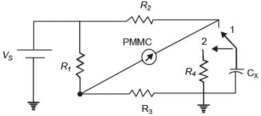
Q. In the bridge circuit shown in the figure above, if the PMMC meter shows null deflection, then the value of CX is

Detailed Solution for Test: Sensor & Industrial Instrumentation- 2 - Question 11

Test: Sensor & Industrial Instrumentation- 2 - Question 12

The diameter of an aluminum sphere is found to be 50 mm at atmospheric pressure of 105 Pa. The bulk modulus for aluminum is 68.6 GPa. The change in the diameter of the sphere in microns, when placed in a vacuum is (2005)

Detailed Solution for Test: Sensor & Industrial Instrumentation- 2 - Question 12
We know Bulk Modulus

=

=>

=>

=> d’ - d = 0.024μm

Test: Sensor & Industrial Instrumentation- 2 - Question 13

In a flyball-type angular speed magnitude measuring device, the centrifugal force, given 10-6 ω2, where ω is the angular speed in rad/s, is transmitted to spring with the non-linear characteristic F = 16π2x2, where F is the applied force and x is the spring compression in meters. The sensitivity of the device in mm.s is (2005)

Detailed Solution for Test: Sensor & Industrial Instrumentation- 2 - Question 13
Fc = 10-6 ω2,

and Fs = 16π2x2

At equilibrium,

10-6 ω2 = 16π2x2

=>

=> dx / dω = 1 / 4π mm.s.

Test: Sensor & Industrial Instrumentation- 2 - Question 14

In a variable-area flowmeter (rotameter), the inlet tube diameter is the same as that of the effective float diameter, and the tube taper is small. When the volume flow rate of a fluid is Q1, the float stands at the height of light from the inlet, and when the volume flow rate of the fluid is Q2, the float moves to a height of 20 mm from the inlet. The ratio of the flow rates Q1 / Q2 is (2005)

Detailed Solution for Test: Sensor & Industrial Instrumentation- 2 - Question 14
Applying Bernauli Theorem

we get, Q1 / Q2 = Q

Test: Sensor & Industrial Instrumentation- 2 - Question 15

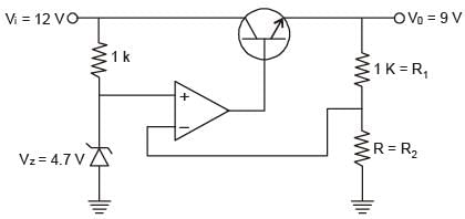
In the voltage regulator shown in the figure, the op-amp is ideal. The BJT has VBE = 0.7 V and β = 100 and Zener voltage Vz is 4.7 V for a regulated output of 9 V the value of R in Ω is____. (2014)

Detailed Solution for Test: Sensor & Industrial Instrumentation- 2 - Question 15

The circuit shown in the figure is an op-amp serif Regulator.

∴ 9R2 = 4.7R2 + 4700

4.3R2 = 4700

∴ R = 1093.023Ω

Test: Sensor & Industrial Instrumentation- 2 - Question 16

In a falling-ball viscometer, the ball attains terminal velocities of 0.01 m/s for oil A and 0.002 m/s for oil B. Assuming the oils have the same density and oil A has a kinematic viscosity of 5 x 10⁻³ m2/s, the kinematic viscosity of oil B in m2/s is 

Detailed Solution for Test: Sensor & Industrial Instrumentation- 2 - Question 16

Applying Stokes formulae, we get the desired result. Here ball obtain terminal velocity because of force applied by liquid due to viscous drag, which is given by formulae F = 6 πnρv

so, kinematic viscosity = 25 × 10– 3m2/s

Test: Sensor & Industrial Instrumentation- 2 - Question 17

A thermometer at room temperature 30°C is dipped suddenly into a bath of boiling water at 100°C. It takes 30 seconds to reach 96.5°C. The time required to reach a temperature of 98 °C is (2005)

Detailed Solution for Test: Sensor & Industrial Instrumentation- 2 - Question 17
Thermometer has been applied a step function at the input (i.e., the thermometer has been suddenly dipped into a bath of boiling water). So it follows an exponential relationship.
Test: Sensor & Industrial Instrumentation- 2 - Question 18

A mercury barometer reads h mm Hg with the temperature of the mercury at T °C. The barometer reading corrected for the standard temperature 0 °C with p denoting the volumetric expansion coefficient of mercury in 0 °C-1, is h (2005)

Detailed Solution for Test: Sensor & Industrial Instrumentation- 2 - Question 18
V(T) = V(1 + βT)

where, V(T) is function of volume as a function of temperature.

Since cross-section area is constant, therefore

ah = V(1 + βT)

=>

so,

Test: Sensor & Industrial Instrumentation- 2 - Question 19

A viscous damper consists of a sliding piston and a cylinder filled with the oil of kinematic viscosity 5 x 10⁻⁵ m2/s. A damping force of 20 N is applied on the piston and the steady-state velocity reached is 10 mm/s. The damping coefficient of the damper is (2004)

Detailed Solution for Test: Sensor & Industrial Instrumentation- 2 - Question 19

where η = damping co-efficient

20 N = η x 10 mm/s

or η = 2 Ns/mm.

Test: Sensor & Industrial Instrumentation- 2 - Question 20

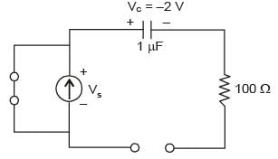
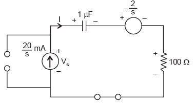
Consider the circuit shown below. Given Vc(0) = - 2V. The value of voltage (VS) across the current source in the circuit is (2014)
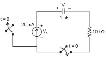

Detailed Solution for Test: Sensor & Industrial Instrumentation- 2 - Question 20

At t = 0

At t = 0+

=>

=>

∴ Vs(t) = 2 × 10⁴t

Test: Sensor & Industrial Instrumentation- 2 - Question 21

A quartz piezo-electric type pressure sensor has a built-in charge amplifier. The sensor has a sensitivity of 1 V/Pa. It is subjected to a constant pressure of 120 kPa. The output of the transducer at a steady state is (2004)

Detailed Solution for Test: Sensor & Industrial Instrumentation- 2 - Question 21
Output voltage = Sensitivity * pressure

= 1 μv / Pa * 120 kPa

= 120 mV

Test: Sensor & Industrial Instrumentation- 2 - Question 22

A pressure sensor has the following specifications Sensitivity at the design temperature = 10 V/MPa, Zero drift = 0.01 V/°C, Sensitivity drift = 0.01 (V/MPa)/°C When the sensor is used in an ambient 20°C above the design temperature, the output from the device is 7.4 V. The true value of the pressure will be (2004)

Detailed Solution for Test: Sensor & Industrial Instrumentation- 2 - Question 22
Output voltage,

V0 = (0.01 V/°C) x 20 + [0.01 (V/MPa)] . 20 Ptrue + 10 Ptrue

or 7.4 =0.2 + 0.01 x 20 P + 10 P

or P = 0.71 MPa.

Test: Sensor & Industrial Instrumentation- 2 - Question 23

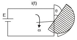
A variable capacitance angular velocity pickup is made with two concentrically mounted parallel semicircular plates with a small separation between them, as shown in Figure. A dc voltage is connected across the terminals of the capacitance sensor, as shown. For a constant angular velocity ω, the waveform of the current i(t) will be (2004)
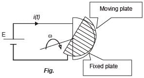
Detailed Solution for Test: Sensor & Industrial Instrumentation- 2 - Question 23
Capacitance between the plates at angle θ,

where, d = plate separation then,

qθ = CθE

i(t) = A constant for dc voltage.

Test: Sensor & Industrial Instrumentation- 2 - Question 24

A strain gauge of resistance 120Ω and gauge factor 2.0 is at zero strain condition A 200 kΩ fixed resistance is connected in parallel with it. Then the combination will represent an equivalent strain of (2004)

Detailed Solution for Test: Sensor & Industrial Instrumentation- 2 - Question 24
Gauge factor,

or,

or,

[-ve sign shows compressive strain]

Test: Sensor & Industrial Instrumentation- 2 - Question 25

A single-sensor, contact-type ultrasonic flaw detector uses a frequency of 330 kHz. When testing a specimen, an echo from a flaw is recorded 0.05 mass after the transmitted pulse. If the velocity of sound in the test object is 6.0 km/s, then the flaw is at a depth of (2004)

Detailed Solution for Test: Sensor & Industrial Instrumentation- 2 - Question 25

= 6 km/s x 0.025 x 10⁻³s

= 15 cm.

Information about Test: Sensor & Industrial Instrumentation- 2 Page
In this test you can find the Exam questions for Test: Sensor & Industrial Instrumentation- 2 solved & explained in the simplest way possible. Besides giving Questions and answers for Test: Sensor & Industrial Instrumentation- 2, EduRev gives you an ample number of Online tests for practice
Download as PDF