GATE Exam  >  GATE Tests  >  Test: Sensor & Industrial Instrumentation- 4 - GATE MCQ

Test: Sensor & Industrial Instrumentation- 4 - GATE MCQ


Test Description

25 Questions MCQ Test - Test: Sensor & Industrial Instrumentation- 4

Test: Sensor & Industrial Instrumentation- 4 for GATE 2024 is part of GATE preparation. The Test: Sensor & Industrial Instrumentation- 4 questions and answers have been prepared according to the GATE exam syllabus.The Test: Sensor & Industrial Instrumentation- 4 MCQs are made for GATE 2024 Exam. Find important definitions, questions, notes, meanings, examples, exercises, MCQs and online tests for Test: Sensor & Industrial Instrumentation- 4 below.
Solutions of Test: Sensor & Industrial Instrumentation- 4 questions in English are available as part of our course for GATE & Test: Sensor & Industrial Instrumentation- 4 solutions in Hindi for GATE course. Download more important topics, notes, lectures and mock test series for GATE Exam by signing up for free. Attempt Test: Sensor & Industrial Instrumentation- 4 | 25 questions in 30 minutes | Mock test for GATE preparation | Free important questions MCQ to study for GATE Exam | Download free PDF with solutions
Test: Sensor & Industrial Instrumentation- 4 - Question 1

The probability that a thermistor randomly picked up from a production unit is defective is 0.1. The probability that out of 10 thermistors randomly picked up, 3 are defective is (2015)

Detailed Solution for Test: Sensor & Industrial Instrumentation- 4 - Question 1

Let p (getting a defective thermistor ) = p = 0.1

Let q (getting a working thermistor ) q = 1 − p = 0.9

Suppose X has a binomial distribution, the probability of x success in n-Bernoulli trials,

Here in this case getting a defective thermistor is success,

p(X = x) = nCx ∗ px ∗ q(n–x)

where in x = 0, 1, 2,..., n some finite number of required successes out of some finite number of trials(n)

Here n = 10 and x = 3

P (3 of thermistors are defective) = p(X = 3)

= 10C3 ∗ p3 ∗ q(10−3)

= 120 ∗ 0.13 ∗ 0.97

= 0.057

Test: Sensor & Industrial Instrumentation- 4 - Question 2

Transconductance characteristics depend on (2014)

Detailed Solution for Test: Sensor & Industrial Instrumentation- 4 - Question 2

Transconductance (for transfer conductance), also infrequently called mutual conductance, is the electrical characteristic relating the current through the output of a device to the voltage across the input of a device. Transadmittance (or transfer admittance) is the AC equivalent of transconductance.

1 Crore+ students have signed up on EduRev. Have you? Download the App
Test: Sensor & Industrial Instrumentation- 4 - Question 3

A psychrometric chart is used to determine (2012)

Detailed Solution for Test: Sensor & Industrial Instrumentation- 4 - Question 3

Psychrometric charts are complex graphs that can be used to assess the physical and thermodynamic properties of gas-vapour mixtures at a constant pressure. They are often used to assess the properties of moist air. Dew point temperature: The highest temperature at which water vapour will condense.

Test: Sensor & Industrial Instrumentation- 4 - Question 4

The conventional way of expressing vibration is in terms of (2011)

Detailed Solution for Test: Sensor & Industrial Instrumentation- 4 - Question 4

The use of weighting networks gives a single number as a measure of vibration exposure and is expressed as the frequency-weighted vibration exposure in meters per second squared (m/s2) units of acceleration.

Test: Sensor & Industrial Instrumentation- 4 - Question 5

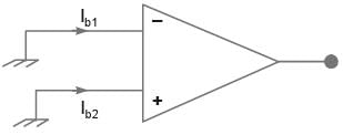
For the op-amp shown in the figure the bias currents are Ib1 = 450nA and Ib2 = 350nA. The values of the input bias current (IB) and the input offset current (If) are: (2014)
Detailed Solution for Test: Sensor & Industrial Instrumentation- 4 - Question 5

Input bias current,

= 400 nA and, Input offset current,

1f = 1b1 - 1b2

= 450 - 350

= 100 nA.

Test: Sensor & Industrial Instrumentation- 4 - Question 6

A sound intensity level of 60 dB corresponds to (2001)

Detailed Solution for Test: Sensor & Industrial Instrumentation- 4 - Question 6

KMw,

Test: Sensor & Industrial Instrumentation- 4 - Question 7

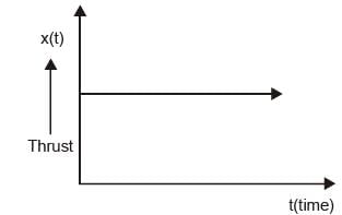
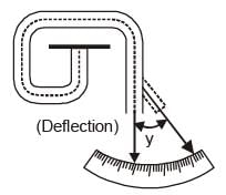
A thrust-producing device is tested in a laboratory by measuring the deflection of a spring element (spring constant K = 750 N/m) attached to the front end of the device. The mass of the device is 25 kg. Assuming that the thrust is idealized as step input to the system. (2002)

(a) Calculate the natural frequency of the system

(b) Calculate the damped natural frequency of the system, if the damping ratio is 0.7

(c) Write the differential equation governing the measuring system


Detailed Solution for Test: Sensor & Industrial Instrumentation- 4 - Question 7
Given, K = 750 N/m

m = 25 kg

For thrust to be step input

(a) ran= Natural frequency

(b) Damping ratio = ε1 = 0.7

∴ damped natural frequency = ωd

= rad 3.83rad/s

(c) For thrust to be step input to governing differential equation of the measuring system is as follows:

where C = damping coefficient.

Test: Sensor & Industrial Instrumentation- 4 - Question 8

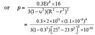
The diaphragm element of a pressure gauge is a circular foil of steel (Young’s modulus, E = 2 x 10¹¹ N/m2, Poisson’s ratio, v = 0.3) which is firmly clamped around its circumference. The radius (R) and thickness (t) of the element are 25 mm and 1.1 mm respectively. On the application of uniform pressure (p), the deflection (y) at any radial position (r) measured from the center is given by the expression: (2002)

(a) Find the maximum design pressure if the allowable deflection of the element is limited to 0.3 times its thickness.

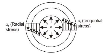
(b) Schematically show the variations of deflection, the radial and tangential stresses from the centerline to the edge of the diaphragm element.


Detailed Solution for Test: Sensor & Industrial Instrumentation- 4 - Question 8
11. Given E = 2 * 1011 N/m2, o = 0.3, R = 25 mm, t = 1.1 mm,

∴ r = R - t = 25 - 1.1 = 23.9 mm

(a)

When y = 0.3 × t

= 11.12 MN/m2

(b)

Test: Sensor & Industrial Instrumentation- 4 - Question 9

An electrical resistance strain gauge of resistance 120Ω has a gauge factor of 2. It is bonded to a steel specimen (modulus of elasticity, E = 2 * 1011 N/m2) for measuring strain. Estimate: (2002)

(a) Strain induced in the specimen if tensile stress of 60 * 106 N/m2 is applied on the specimen.

(b) Change in the electrical resistance of the gauge due to the tensile stress as given in (a)

(c) Change in the electrical resistance of the gauge if there is an increase of temperature by 40°C.

Assume the following data:

Temperature coefficient of resistance of gauge is 20 * 10-6 per °C

Thermal coefficient of linear expansion of the gauge is 16 * 10-6 per °C.

Thermal coefficient of linear expansion of steel specimen is 12 * 10-6 per °C.


Detailed Solution for Test: Sensor & Industrial Instrumentation- 4 - Question 9
Given R = Resistance = 120Ω

Gf = Gauge factor = 2

E = 2 x 10¹¹ N/m2

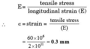
(a) Tensile stress = 60 x 106 N/m2

We know that,

where ΔR = change in resistance

∴ ΔR = Gf x ε x R

= 2 x 0.3 x 10-3 x 120

= 0.072Ω

(c) ΔT = increase of temperature = 40°C

AR1 = change in resistance due to temperature increase

= R (1 + αg ΔT) = 120 (1 + 20 x 106 x 40) = 120.096Ω

where αg = temperature coefficient of resistance of gauge.

Test: Sensor & Industrial Instrumentation- 4 - Question 10

A hollow circular steel shaft (shear modulus G = 8 x 10¹⁰ N/m2) with outer and inner radii of 33 mm and 25 mm respectively, has a length of 150 mm. It is transmitting a torque of T N-m. The strain indicated by a strain gauge fixed on the outer periphery at an angle of 45° to the axis of the shaft is 5.5 microstrain (micrometer per meter). Estimate the value of T and the angular deflection of the shaft. (2002)


Detailed Solution for Test: Sensor & Industrial Instrumentation- 4 - Question 10
Given: G =8 x 10¹⁰ N/m2

R0 = outer radius = 33 mm

Ri = inner radius = 25 mm

l = 150 mm

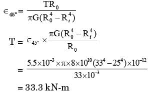
T = torque 0 = 45° = π/4, ε45° = strain = 5.5 x 10⁻³ m/m

We know that strain induced

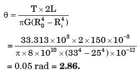
Again from the Torsion formula,

where θ = angular deflection of the shaft

Test: Sensor & Industrial Instrumentation- 4 - Question 11

A calibrated orifice meter is used in a pipeline of 103 mm ID to calibrate the probe of a constant temperature hotwire anemometer (CTA). The orifice meter readings are recorded in mm of Hg and the CTA readings in volts. It is independently found that the average velocity in the pipeline is exactly equal to the velocity at its axis, the volume flow rate of the fluid (Q) can be measured from the orifice meter calibration equation: Q = 6.311 x 10⁻⁴√h where h is in mm of Hg and Q is in m3/s. The readings of the CTA are correlated in the form : (volt)2 = a + b (velocity)1/2. Determine the constants (a) and (b) in this equation if the voltage readings are 0.284 and 0.323 V respectively when the corresponding orifice meter readings are 77 and 154 mm Hg. (5) (2002)


Detailed Solution for Test: Sensor & Industrial Instrumentation- 4 - Question 11
Given: Di = inner diameter = 103 mm.

Q = 6.311 x 10⁻⁴ √h, h = mm of Hg ...(i)

(Volt)2 = a + b (Velocity)1/2...(ii)

E1 = 0.284 V

when h1 = 77 mm Hg

E2 = 0.323 V

when h2 = 154 mm Hg

From equation (i),

when h1 = 77 mm Hg,

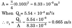
Q1 = 6.311 x 10⁻⁴ √77 = 5.54 x 10⁻³ m3/s

when h2 = 154 mm Hg,

Q2 = 6.311 x 10⁻⁴ x √154 = 7.83 x 10⁻³ m3/s

From continuity equation, Q = A.v,

where A = Area v = velocity

Test: Sensor & Industrial Instrumentation- 4 - Question 12

During measurement of pressure by an elastic transducer, pressure is instantaneously changed in a stepwise manner from 5 bar to 30 bar. The transducer indicates a value of 20 bar after 30 secs. Assume that the transducer is a first-order instrument. (2001)

(a) Determine the time constant of the transducer.

(b) How much time will the transducer take to indicate the pressure within 5% of the final value?

(c) On what factors does the time constant of the elastic transducer depend?


Detailed Solution for Test: Sensor & Industrial Instrumentation- 4 - Question 12

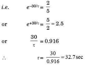
where P = pressure at any time bar after time of 30 sec

P0 = final pressure = 30 bar

Pi = initial pressure = 5 bar

Test: Sensor & Industrial Instrumentation- 4 - Question 13

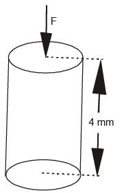
A piezoelectric transducer having diameter = 8 mm, thickness = 4 mm, charge sensitivity = 2 x 10-12 C/N, dielectric constant = 4 x 10-11 F/m and modulus of elasticity = 8.6 x 10¹⁰ N/m2 is used for the measurement of small displacement. For an input displacement of 109 m, determine

(a) the force to which it is subjected,

(b) the capacitance of the transducer,

(c) the charge generated,

(d) the voltage developed


Detailed Solution for Test: Sensor & Industrial Instrumentation- 4 - Question 13
Given,Input displacement = 10-9 m

y = 8.6 x 10¹⁰ N/m2

Dielectric constant = 4 x 10-11 F/m

Charge sensitivity, d = 2 x 10-12 C/N

Charge generated, Q = d x F

where, d = charge sensitivity

f = force in N

A = πr2

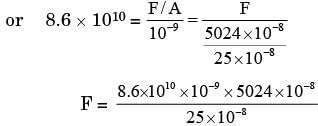
Strain in transducer

= 1.08 x 10⁶ N

Q = d x F

= 1.08 x 106 x 2 x 10-12

= 2.16 x 10⁻⁶ C

Voltage generated, E0 = gtp

Test: Sensor & Industrial Instrumentation- 4 - Question 14

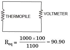
A thermopile having a resitance of 100 Q and consisting of 20 copper-constantan thermocouples is used to measure temperature difference between two points. The temperature of the first point measured separately is 25°C. EMF generated measured by a voltage measuring device having an internal resistance of 1000 Q is 1.47 mV. E MF-temperature relationship for copper-constantan thermocouple with reference junction at 0° is as follows. (2001)
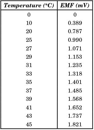
Determine the temperature difference between the two points after applying a correction for loading effect in the measurement of the EMF.


Detailed Solution for Test: Sensor & Industrial Instrumentation- 4 - Question 14
The thermocouple output is directly proportional to the temperature difference between hot and cold junction. Junction RJ is at a temperature of 25°C.

The internal resistance of voltmeter of resistance 1000Ω having a voltage of 1.47 mV

Test: Sensor & Industrial Instrumentation- 4 - Question 15

A certain pressure transducer measures the stagnation pressure (the total pressure). The density of the fluid is 1.03 g/cm3 and the velocity of flow is 100 cm/s. (2001)

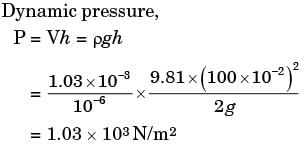
(a) Calculate the dynamic pressure (pressure due to the velocity of flow) in N/m2.

(b) If the total pressure measured by the transducer is 10000 N/m2, find the static pressure in mm of Hg.


Detailed Solution for Test: Sensor & Industrial Instrumentation- 4 - Question 15
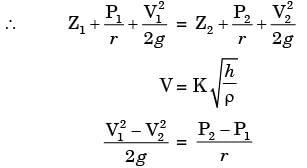
Static pressure = rgh

(a) Dynamic load

(b) Total pressure = pgh

or 10,000 N/m2, = 1,000 x 9.8 x h

Test: Sensor & Industrial Instrumentation- 4 - Question 16

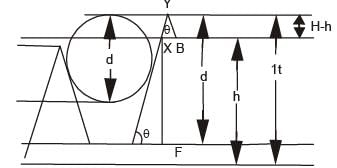
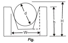
The width of a V-groove shown in Figure is determined using a standard steel ball of diameter d and a vernier height gauge. (2001)

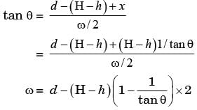
(a) If the angle of the groove is A, derive an expression for the width w of the V-groove.

(b) Given: d = 30 mm, H = 50 mm, h = 45 mm and a = 60°, calculate w.

Detailed Solution for Test: Sensor & Industrial Instrumentation- 4 - Question 16
(a)

In ΔABC

In ΔCDF

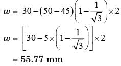
(b) d = 30 mm, H = 50 mm, h = 45 mm, A = 60 = 9

Test: Sensor & Industrial Instrumentation- 4 - Question 17

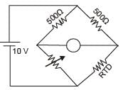
An RTD has a resistance of 500Ω at 20°C and a temperature co-efficient of 0.005/°C at 0°C. The RTD is used in a Wheatstone bridge circuit with R1 = R2 = 500Ω. The variable resistor R3 nulls the bridge. If the bridge supply is 10 V and the RTD is in a both of 0°C, find the values of R3 to null the bridge when (2000)

(a) No self-heating of RTD is considered

(b) Self-heating of RTD is considered and the dissipation constant of the RTD is 20 mW/°C.


Detailed Solution for Test: Sensor & Industrial Instrumentation- 4 - Question 17
Given α = 0.005 at 0°C

t = 20°C

Rt20 = 500Ω

Now, Rt = R0 [1 + α (T - T0)]

or 500 = 1.1 R0

or R0 = 500 / 1.1 = 454.54Ω

(a) without heating effect is 454.54Ω

(b) Dissipating constant = 20 m W/°C

Test: Sensor & Industrial Instrumentation- 4 - Question 18

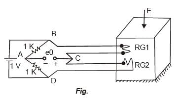
Two identical strain gauges of resistance 120Ω and gauge factor + 2.0 each are attached to a steel block of Poisson’s ratio V = 0.3 as shown in Figure. Find the unbalance voltage per unit microstrain applied to the steel block as shown. (2000)

Detailed Solution for Test: Sensor & Industrial Instrumentation- 4 - Question 18
R = 120Ω V = 30 CTp = 2 e1 = 1V

ε = strain/micro stain developed

Change in O/P when strain gauge is applied

For half-bridge,

Hence for every unit microstrain applied

Test: Sensor & Industrial Instrumentation- 4 - Question 19

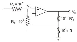
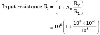
A pH electrode is connected through a shielded cable to a non-inverting amplifier as shown in Figure. The resistance of the electrode is 109Ω and the leakage resistance of the shielded cable is also 109Ω. Given that the input resistance of the non-inverting amplifier is, (2000)

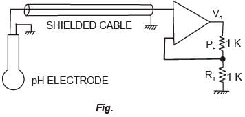
where A0 is the open-loop gain and R is the input resistance of the op-amp, find the output voltage v0 when a 100 mV signal is generated at the electrode. Assume R = 106Ω and A = 105 for i0 the op-amp used.


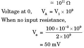
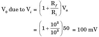
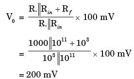
Detailed Solution for Test: Sensor & Industrial Instrumentation- 4 - Question 19
Resistance of electrode R2 = 109 Ω

Leakage Resistance R3 = 109Ω

Ao = 105 R = 106Ω

Vi = 100 mVi

When input resistance is considered

Test: Sensor & Industrial Instrumentation- 4 - Question 20

The e.m.f. developed by a photovoltaic cell can be taken as proportional to the logarithm of the intensity of radiation impinging on it. For 10 W/ m2 radiation, a cell develops an e.m.f. of 0.33 V and drives a current of 2.2 mA into a 100Ω load. Calculate: (2000)

(a) The open-circuit voltage at 25 W/m2.

(b) The internal resistance of the cell.


Detailed Solution for Test: Sensor & Industrial Instrumentation- 4 - Question 20
We know that e0 is directly proportional to logarithmic at I

i.e. e0 α log10 I

where I = 10 W/m2

e0 = K log10 10

=> 0.33 = K

(a) Given that I = 25 W/m2

e0 = K log10 I

e0 = K log10 25

= 0.33 log10 25

= 0.33 x 1.4 = 0.461 V

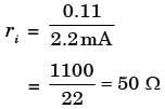
(b) R = 100Ω

I = 2.2 mA

V = IR

= 2.2 x 100 = 0.22 V

Internally dropped potential

= (0.33 - 0.22) V = 0.11V

Test: Sensor & Industrial Instrumentation- 4 - Question 21

Kelvin double bridge is best suited for the measurement of (2002)

Test: Sensor & Industrial Instrumentation- 4 - Question 22

A seismic type of transducer has a damping constant of 10. The transducer is designed to measure (2002)

Test: Sensor & Industrial Instrumentation- 4 - Question 23

All metal resistive strain gauges have a gauge factor (GF) of nearly 2.5 due to the (2002)

Test: Sensor & Industrial Instrumentation- 4 - Question 24

A common practice of reducing hysteresis error in the output for a given value of the input is to maintain (2002)

Test: Sensor & Industrial Instrumentation- 4 - Question 25

A pitot-static tube is used for measuring the velocity of the gas, flowing in a duct. The velocity is proportional to

Information about Test: Sensor & Industrial Instrumentation- 4 Page
In this test you can find the Exam questions for Test: Sensor & Industrial Instrumentation- 4 solved & explained in the simplest way possible. Besides giving Questions and answers for Test: Sensor & Industrial Instrumentation- 4, EduRev gives you an ample number of Online tests for practice
Download as PDF