Case Based Questions Test: Alternating Current - Grade 12 MCQ
15 Questions MCQ Test - Case Based Questions Test: Alternating Current

Read the following text and answer the following questions on the basis of the same:
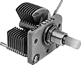
Tuning a radio set: In essence the simplest tuned radio frequency receiver is a simple crystal set. Desired frequency is tuned by a tuned coil / capacitor combination, and then the signal is presented to a simple crystal or diode detector where the amplitude modulated signal, is demodulated. This is then passed straight to the headphones or speaker. In radio set there is an LC oscillator comprising of a variable capacitor (or sometimes a variable coupling coil), with a knob on the front panel to tune the receiver. Capacitor used in old radio sets is gang capacitor. It consists of two sets of parallel circular plates one of which can rotate manually by means of a knob. The rotation causes overlapping areas of plates to change, thus changing its capacitance. Air gap between plates acts as dielectric. The capacitor has to be tuned in tandem corresponding to the frequency of a station so that the LC combination of the radio set resonates at the frequency of the desired station.

When capacitive reactance (XC) is equal to the inductive reactance (XL), then the resonance occurs and the resonant frequency is given by ω0 = 1/√LC
current amplitude becomes maximum at the resonant frequency. It is important to note that resonance phenomenon is exhibited by a circuit only if both L and C are present in the circuit. Only then do the voltages across L and C cancel each other (both being out of phase) and the Current amplitude is Vm/R the total source voltage appearing across R. This means that we cannot have resonance in a RL or RC circuit.
Name the phenomenon involved in tuning a radio set to a particular radio station.
Read the following text and answer the following questions on the basis of the same: Tuning a radio set: In essence the simplest tuned radio frequency receiver is a simple crystal set. Desired frequency is tuned by a tuned coil / capacitor combination, and then the signal is presented to a simple crystal or diode detector where the amplitude modulated signal, is demodulated. This is then passed straight to the headphones or speaker. In radio set there is an LC oscillator comprising of a variable capacitor (or sometimes a variable coupling coil), with a knob on the front panel to tune the receiver. Capacitor used in old radio sets is gang capacitor. It consists of two sets of parallel circular plates one of which can rotate manually by means of a knob. The rotation causes overlapping areas of plates to change, thus changing its capacitance. Air gap between plates acts as dielectric. The capacitor has to be tuned in tandem corresponding to the frequency of a station so that the LC combination of the radio set resonates at the frequency of the desired station.

When capacitive reactance (XC) is equal to the inductive reactance (XL), then the resonance occurs and the resonant frequency is given by ω0 = 1/√LC
current amplitude becomes maximum at the resonant frequency. It is important to note that resonance phenomenon is exhibited by a circuit only if both L and C are present in the circuit. Only then do the voltages across L and C cancel each other (both being out of phase) and the Current amplitude is Vm/R the total source voltage appearing across R. This means that we cannot have resonance in a RL or RC circuit.
Resonance frequency is equal to:

Read the following text and answer the following questions on the basis of the same: Tuning a radio set: In essence the simplest tuned radio frequency receiver is a simple crystal set. Desired frequency is tuned by a tuned coil / capacitor combination, and then the signal is presented to a simple crystal or diode detector where the amplitude modulated signal, is demodulated. This is then passed straight to the headphones or speaker. In radio set there is an LC oscillator comprising of a variable capacitor (or sometimes a variable coupling coil), with a knob on the front panel to tune the receiver. Capacitor used in old radio sets is gang capacitor. It consists of two sets of parallel circular plates one of which can rotate manually by means of a knob. The rotation causes overlapping areas of plates to change, thus changing its capacitance. Air gap between plates acts as dielectric. The capacitor has to be tuned in tandem corresponding to the frequency of a station so that the LC combination of the radio set resonates at the frequency of the desired station.

When capacitive reactance (XC) is equal to the inductive reactance (XL), then the resonance occurs and the resonant frequency is given by ω0 = 1/√LC
current amplitude becomes maximum at the resonant frequency. It is important to note that resonance phenomenon is exhibited by a circuit only if both L and C are present in the circuit. Only then do the voltages across L and C cancel each other (both being out of phase) and the Current amplitude is Vm/R the total source voltage appearing across R. This means that we cannot have resonance in a RL or RC circuit.
Capacitor used in radio set for tuning is a:
Read the following text and answer the following questions on the basis of the same:
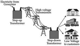
At power plant, a transformer increases the voltage of generated power by thousands of volts so that it can be sent of long distances through high-voltage transmission power lines. Transmission lines are bundles of wires that carry electric power from power plants to distant substations. At substations, transformers lower the voltage of incoming power to make it acceptable for high volume delivery to nearby end-users. Electricity is sent at extremely high voltage because it limits so-called line losses. Very good conductors of electricity also offer some resistance and this resistance becomes considerable over long distances causing considerable loss.

At generating station, normally voltage is stepped up to around thousands of volts. Power losses increase with the square of current. Therefore, keeping voltage high current becomes low and the loss is minimized. Another option of minimizing loss is the use of wires of superconducting material. Super-conducting materials are capable of conducting without resistance, they must be kept extremely cold, nearly absolute zero, and this requirement makes standard superconducting materials impractical to use. However, recent advances in superconducting materials have decreased cooling requirements. In Germany recently 1 km of superconducting cable have been installed connecting the generating station and the destination. It has eliminated the line loss and the cable is capable of sending five times more electricity than conventional cable. Using superconducting cables Germany has also get rid of the need of costly transformers. Transformers generate waste heat when they are in operation and oil is the coolant of choice. It transfers the heat through convection to the transformer housing, which has cooling fins or radiators similar to heat exchangers on the outside. Flush point is a very important parameter of transformer oil. Flashpoint of an oil is the temperature at which the oil ignites spontaneously. This must be as high as possible (not less than 160° C from the point of safety). Fire point is the temperature at which the oil flashes and continuously burns. This must be very high for the chosen oil (not less than 200° C).
Which of the following statement is true for long distance transmission of electricity?
Read the following text and answer the following questions on the basis of the same: At power plant, a transformer increases the voltage of generated power by thousands of volts so that it can be sent of long distances through high-voltage transmission power lines. Transmission lines are bundles of wires that carry electric power from power plants to distant substations. At substations, transformers lower the voltage of incoming power to make it acceptable for high volume delivery to nearby end-users. Electricity is sent at extremely high voltage because it limits so-called line losses. Very good conductors of electricity also offer some resistance and this resistance becomes considerable over long distances causing considerable loss.

At generating station, normally voltage is stepped up to around thousands of volts. Power losses increase with the square of current. Therefore, keeping voltage high current becomes low and the loss is minimized. Another option of minimizing loss is the use of wires of superconducting material. Super-conducting materials are capable of conducting without resistance, they must be kept extremely cold, nearly absolute zero, and this requirement makes standard superconducting materials impractical to use. However, recent advances in superconducting materials have decreased cooling requirements. In Germany recently 1 km of superconducting cable have been installed connecting the generating station and the destination. It has eliminated the line loss and the cable is capable of sending five times more electricity than conventional cable. Using superconducting cables Germany has also get rid of the need of costly transformers. Transformers generate waste heat when they are in operation and oil is the coolant of choice. It transfers the heat through convection to the transformer housing, which has cooling fins or radiators similar to heat exchangers on the outside. Flush point is a very important parameter of transformer oil. Flashpoint of an oil is the temperature at which the oil ignites spontaneously. This must be as high as possible (not less than 160° C from the point of safety). Fire point is the temperature at which the oil flashes and continuously burns. This must be very high for the chosen oil (not less than 200° C).
Why does stepping up voltages reduce power loss?
Read the following text and answer the following questions on the basis of the same: At power plant, a transformer increases the voltage of generated power by thousands of volts so that it can be sent of long distances through high-voltage transmission power lines. Transmission lines are bundles of wires that carry electric power from power plants to distant substations. At substations, transformers lower the voltage of incoming power to make it acceptable for high volume delivery to nearby end-users. Electricity is sent at extremely high voltage because it limits so-called line losses. Very good conductors of electricity also offer some resistance and this resistance becomes considerable over long distances causing considerable loss.

At generating station, normally voltage is stepped up to around thousands of volts. Power losses increase with the square of current. Therefore, keeping voltage high current becomes low and the loss is minimized. Another option of minimizing loss is the use of wires of superconducting material. Super-conducting materials are capable of conducting without resistance, they must be kept extremely cold, nearly absolute zero, and this requirement makes standard superconducting materials impractical to use. However, recent advances in superconducting materials have decreased cooling requirements. In Germany recently 1 km of superconducting cable have been installed connecting the generating station and the destination. It has eliminated the line loss and the cable is capable of sending five times more electricity than conventional cable. Using superconducting cables Germany has also get rid of the need of costly transformers. Transformers generate waste heat when they are in operation and oil is the coolant of choice. It transfers the heat through convection to the transformer housing, which has cooling fins or radiators similar to heat exchangers on the outside. Flush point is a very important parameter of transformer oil. Flashpoint of an oil is the temperature at which the oil ignites spontaneously. This must be as high as possible (not less than 160° C from the point of safety). Fire point is the temperature at which the oil flashes and continuously burns. This must be very high for the chosen oil (not less than 200° C).
Flush point of an oil is
Read the following text and answer the following questions on the basis of the same:
Losses of transformer
There are 4 types of losses in a transformer: Core loss, Ohmic loss, Stray load loss and dielectric loss.
(1) Core loss Core loss has two components - hysteresis loss and eddy current loss. These together are called no-load losses of a transformer and are calculated by open circuit test.
(a) Hysteresis loss: This loss mainly depends on the core material used in the transformer. To reduce this loss, the high-grade core material can be used. CRGO- Cold rolled grain oriented Si steel is commonly used for this purpose.
(b) Eddy current loss: This loss can be reduced by designing the core using slight laminations. These losses are present even when no load is connected. So, these are also known as no-load loss.
(2) Copper Loss Copper losses occur because of the Ohmic resistance in the windings of the transformer. If the currents in primary and secondary windings of the transformer are I1 and I2, and if the resistances of these windings are R1 & R2 then the copper losses that occurred in the windings are I12R1 & I22R2 respectively. So, the entire copper loss will be I12R1 + I22R2. This loss is also called variable or ohmic losses because this loss changes based on the load.
(3) Stray Loss These types of losses in a transformer occur because of the occurrence of the leakage flux. As compared with copper and iron losses, the percentage of stray losses are less, so these losses can be neglected.
(4) Dielectric Loss This loss mainly occurs within the oil of the transformer. Oil is an insulating material. Once the oil quality in the transformer deteriorates then the transformer’s efficiency is affected. Efficiency of a Transformer It is the ratio of output power and input power. Efficiency = Output Power / Input Power. The transformer is a highly efficient device which ranges between 95% – 98.5%.
What is the relationship among core loss, hysteresis loss and eddy current loss?
Read the following text and answer the following questions on the basis of the same:
Losses of transformer
There are 4 types of losses in a transformer: Core loss, Ohmic loss, Stray load loss and dielectric loss.
(1) Core loss Core loss has two components - hysteresis loss and eddy current loss. These together are called no-load losses of a transformer and are calculated by open circuit test.
(a) Hysteresis loss: This loss mainly depends on the core material used in the transformer. To reduce this loss, the high-grade core material can be used. CRGO- Cold rolled grain oriented Si steel is commonly used for this purpose.
(b) Eddy current loss: This loss can be reduced by designing the core using slight laminations. These losses are present even when no load is connected. So, these are also known as no-load loss.
(2) Copper Loss Copper losses occur because of the Ohmic resistance in the windings of the transformer. If the currents in primary and secondary windings of the transformer are I1 and I2, and if the resistances of these windings are R1 & R2 then the copper losses that occurred in the windings are I12R1 & I22R2 respectively. So, the entire copper loss will be I12R1 + I22R2. This loss is also called variable or ohmic losses because this loss changes based on the load.
(3) Stray Loss These types of losses in a transformer occur because of the occurrence of the leakage flux. As compared with copper and iron losses, the percentage of stray losses are less, so these losses can be neglected.
(4) Dielectric Loss This loss mainly occurs within the oil of the transformer. Oil is an insulating material. Once the oil quality in the transformer deteriorates then the transformer’s efficiency is affected. Efficiency of a Transformer It is the ratio of output power and input power. Efficiency = Output Power / Input Power. The transformer is a highly efficient device which ranges between 95% – 98.5%.
Which of the following losses in transformer is also known as variable loss?
Read the following text and answer the following questions on the basis of the same:
Losses of transformer
There are 4 types of losses in a transformer: Core loss, Ohmic loss, Stray load loss and dielectric loss.
(1) Core loss Core loss has two components - hysteresis loss and eddy current loss. These together are called no-load losses of a transformer and are calculated by open circuit test.
(a) Hysteresis loss: This loss mainly depends on the core material used in the transformer. To reduce this loss, the high-grade core material can be used. CRGO- Cold rolled grain oriented Si steel is commonly used for this purpose.
(b) Eddy current loss: This loss can be reduced by designing the core using slight laminations. These losses are present even when no load is connected. So, these are also known as no-load loss.
(2) Copper Loss Copper losses occur because of the Ohmic resistance in the windings of the transformer. If the currents in primary and secondary windings of the transformer are I1 and I2, and if the resistances of these windings are R1 & R2 then the copper losses that occurred in the windings are I12R1 & I22R2 respectively. So, the entire copper loss will be I12R1 + I22R2. This loss is also called variable or ohmic losses because this loss changes based on the load.
(3) Stray Loss These types of losses in a transformer occur because of the occurrence of the leakage flux. As compared with copper and iron losses, the percentage of stray losses are less, so these losses can be neglected.
(4) Dielectric Loss This loss mainly occurs within the oil of the transformer. Oil is an insulating material. Once the oil quality in the transformer deteriorates then the transformer’s efficiency is affected. Efficiency of a Transformer It is the ratio of output power and input power. Efficiency = Output Power / Input Power. The transformer is a highly efficient device which ranges between 95% – 98.5%.
Specify the range of transformer efficiency.
Read the following text and answer the following questions on the basis of the same:
Tuning a radio set: In essence the simplest tuned radio frequency receiver is a simple crystal set. Desired frequency is tuned by a tuned coil / capacitor combination, and then the signal is presented to a simple crystal or diode detector where the amplitude modulated signal, is demodulated. This is then passed straight to the headphones or speaker. In radio set there is an LC oscillator comprising of a variable capacitor (or sometimes a variable coupling coil), with a knob on the front panel to tune the receiver. Capacitor used in old radio sets is gang capacitor. It consists of two sets of parallel circular plates one of which can rotate manually by means of a knob. The rotation causes overlapping areas of plates to change, thus changing its capacitance. Air gap between plates acts as dielectric. The capacitor has to be tuned in tandem corresponding to the frequency of a station so that the LC combination of the radio set resonates at the frequency of the desired station.
When capacitive reactance (XC) is equal to the inductive reactance (XL), then the resonance occurs and the resonant frequency is given by ω0 = 1/√LC
current amplitude becomes maximum at the resonant frequency. It is important to note that resonance phenomenon is exhibited by a circuit only if both L and C are present in the circuit. Only then do the voltages across L and C cancel each other (both being out of phase) and the Current amplitude is Vm/R the total source voltage appearing across R. This means that we cannot have resonance in a RL or RC circuit.
Resonance may occur in:
Read the following text and answer the following questions on the basis of the same: Tuning a radio set: In essence the simplest tuned radio frequency receiver is a simple crystal set. Desired frequency is tuned by a tuned coil / capacitor combination, and then the signal is presented to a simple crystal or diode detector where the amplitude modulated signal, is demodulated. This is then passed straight to the headphones or speaker. In radio set there is an LC oscillator comprising of a variable capacitor (or sometimes a variable coupling coil), with a knob on the front panel to tune the receiver. Capacitor used in old radio sets is gang capacitor. It consists of two sets of parallel circular plates one of which can rotate manually by means of a knob. The rotation causes overlapping areas of plates to change, thus changing its capacitance. Air gap between plates acts as dielectric. The capacitor has to be tuned in tandem corresponding to the frequency of a station so that the LC combination of the radio set resonates at the frequency of the desired station.

When capacitive reactance (XC) is equal to the inductive reactance (XL), then the resonance occurs and the resonant frequency is given by ω0 = 1/√LC
current amplitude becomes maximum at the resonant frequency. It is important to note that resonance phenomenon is exhibited by a circuit only if both L and C are present in the circuit. Only then do the voltages across L and C cancel each other (both being out of phase) and the Current amplitude is Vm/R the total source voltage appearing across R. This means that we cannot have resonance in a RL or RC circuit.
Resonance occurs only when:
Read the following text and answer the following questions on the basis of the same: At power plant, a transformer increases the voltage of generated power by thousands of volts so that it can be sent of long distances through high-voltage transmission power lines. Transmission lines are bundles of wires that carry electric power from power plants to distant substations. At substations, transformers lower the voltage of incoming power to make it acceptable for high volume delivery to nearby end-users. Electricity is sent at extremely high voltage because it limits so-called line losses. Very good conductors of electricity also offer some resistance and this resistance becomes considerable over long distances causing considerable loss.

At generating station, normally voltage is stepped up to around thousands of volts. Power losses increase with the square of current. Therefore, keeping voltage high current becomes low and the loss is minimized. Another option of minimizing loss is the use of wires of superconducting material. Super-conducting materials are capable of conducting without resistance, they must be kept extremely cold, nearly absolute zero, and this requirement makes standard superconducting materials impractical to use. However, recent advances in superconducting materials have decreased cooling requirements. In Germany recently 1 km of superconducting cable have been installed connecting the generating station and the destination. It has eliminated the line loss and the cable is capable of sending five times more electricity than conventional cable. Using superconducting cables Germany has also get rid of the need of costly transformers. Transformers generate waste heat when they are in operation and oil is the coolant of choice. It transfers the heat through convection to the transformer housing, which has cooling fins or radiators similar to heat exchangers on the outside. Flush point is a very important parameter of transformer oil. Flashpoint of an oil is the temperature at which the oil ignites spontaneously. This must be as high as possible (not less than 160° C from the point of safety). Fire point is the temperature at which the oil flashes and continuously burns. This must be very high for the chosen oil (not less than 200° C).
Superconducting transmission line has the following advantages:
Read the following text and answer the following questions on the basis of the same:
At power plant, a transformer increases the voltage of generated power by thousands of volts so that it can be sent of long distances through high-voltage transmission power lines. Transmission lines are bundles of wires that carry electric power from power plants to distant substations. At substations, transformers lower the voltage of incoming power to make it acceptable for high volume delivery to nearby end-users. Electricity is sent at extremely high voltage because it limits so-called line losses. Very good conductors of electricity also offer some resistance and this resistance becomes considerable over long distances causing considerable loss.
At generating station, normally voltage is stepped up to around thousands of volts. Power losses increase with the square of current. Therefore, keeping voltage high current becomes low and the loss is minimized. Another option of minimizing loss is the use of wires of superconducting material. Super-conducting materials are capable of conducting without resistance, they must be kept extremely cold, nearly absolute zero, and this requirement makes standard superconducting materials impractical to use. However, recent advances in superconducting materials have decreased cooling requirements. In Germany recently 1 km of superconducting cable have been installed connecting the generating station and the destination. It has eliminated the line loss and the cable is capable of sending five times more electricity than conventional cable. Using superconducting cables Germany has also get rid of the need of costly transformers. Transformers generate waste heat when they are in operation and oil is the coolant of choice. It transfers the heat through convection to the transformer housing, which has cooling fins or radiators similar to heat exchangers on the outside. Flush point is a very important parameter of transformer oil. Flashpoint of an oil is the temperature at which the oil ignites spontaneously. This must be as high as possible (not less than 160° C from the point of safety). Fire point is the temperature at which the oil flashes and continuously burns. This must be very high for the chosen oil (not less than 200° C).
Oil transfers heat from transformer winding by the process of:
Read the following text and answer the following questions on the basis of the same:
Losses of transformer
There are 4 types of losses in a transformer: Core loss, Ohmic loss, Stray load loss and dielectric loss.
(1) Core loss Core loss has two components - hysteresis loss and eddy current loss. These together are called no-load losses of a transformer and are calculated by open circuit test.
(a) Hysteresis loss: This loss mainly depends on the core material used in the transformer. To reduce this loss, the high-grade core material can be used. CRGO- Cold rolled grain oriented Si steel is commonly used for this purpose.
(b) Eddy current loss: This loss can be reduced by designing the core using slight laminations. These losses are present even when no load is connected. So, these are also known as no-load loss.
(2) Copper Loss Copper losses occur because of the Ohmic resistance in the windings of the transformer. If the currents in primary and secondary windings of the transformer are I1 and I2, and if the resistances of these windings are R1 & R2 then the copper losses that occurred in the windings are I12R1 & I22R2 respectively. So, the entire copper loss will be I12R1 + I22R2. This loss is also called variable or ohmic losses because this loss changes based on the load.
(3) Stray Loss These types of losses in a transformer occur because of the occurrence of the leakage flux. As compared with copper and iron losses, the percentage of stray losses are less, so these losses can be neglected.
(4) Dielectric Loss This loss mainly occurs within the oil of the transformer. Oil is an insulating material. Once the oil quality in the transformer deteriorates then the transformer’s efficiency is affected. Efficiency of a Transformer It is the ratio of output power and input power. Efficiency = Output Power / Input Power. The transformer is a highly efficient device which ranges between 95% – 98.5%.
Which of the following losses in transformer is also known as no-load loss?
Read the following text and answer the following questions on the basis of the same:
Losses of transformer
There are 4 types of losses in a transformer: Core loss, Ohmic loss, Stray load loss and dielectric loss.
(1) Core loss Core loss has two components - hysteresis loss and eddy current loss. These together are called no-load losses of a transformer and are calculated by open circuit test.
(a) Hysteresis loss: This loss mainly depends on the core material used in the transformer. To reduce this loss, the high-grade core material can be used. CRGO- Cold rolled grain oriented Si steel is commonly used for this purpose.
(b) Eddy current loss: This loss can be reduced by designing the core using slight laminations. These losses are present even when no load is connected. So, these are also known as no-load loss.
(2) Copper Loss Copper losses occur because of the Ohmic resistance in the windings of the transformer. If the currents in primary and secondary windings of the transformer are I1 and I2, and if the resistances of these windings are R1 & R2 then the copper losses that occurred in the windings are I12R1 & I22R2 respectively. So, the entire copper loss will be I12R1 + I22R2. This loss is also called variable or ohmic losses because this loss changes based on the load.
(3) Stray Loss These types of losses in a transformer occur because of the occurrence of the leakage flux. As compared with copper and iron losses, the percentage of stray losses are less, so these losses can be neglected.
(4) Dielectric Loss This loss mainly occurs within the oil of the transformer. Oil is an insulating material. Once the oil quality in the transformer deteriorates then the transformer’s efficiency is affected. Efficiency of a Transformer It is the ratio of output power and input power. Efficiency = Output Power / Input Power. The transformer is a highly efficient device which ranges between 95% – 98.5%.
How hysteresis loss can be reduced?


Important Questions for Case Based Questions Test: Alternating Current
Case Based Questions Test: Alternating Current MCQs with Answers
Online Tests for Case Based Questions Test: Alternating Current
|
© EduRev
|
Education Revolution
|


|


