Electronics and Communication Engineering (ECE) Exam  >  Electronics and Communication Engineering (ECE) Tests  >  Test: Dependent & Independent Sources - 2 - Electronics and Communication Engineering (ECE) MCQ

Test: Dependent & Independent Sources - 2 - Electronics and Communication Engineering (ECE) MCQ


Test Description

15 Questions MCQ Test - Test: Dependent & Independent Sources - 2

Test: Dependent & Independent Sources - 2 for Electronics and Communication Engineering (ECE) 2024 is part of Electronics and Communication Engineering (ECE) preparation. The Test: Dependent & Independent Sources - 2 questions and answers have been prepared according to the Electronics and Communication Engineering (ECE) exam syllabus.The Test: Dependent & Independent Sources - 2 MCQs are made for Electronics and Communication Engineering (ECE) 2024 Exam. Find important definitions, questions, notes, meanings, examples, exercises, MCQs and online tests for Test: Dependent & Independent Sources - 2 below.
Solutions of Test: Dependent & Independent Sources - 2 questions in English are available as part of our course for Electronics and Communication Engineering (ECE) & Test: Dependent & Independent Sources - 2 solutions in Hindi for Electronics and Communication Engineering (ECE) course. Download more important topics, notes, lectures and mock test series for Electronics and Communication Engineering (ECE) Exam by signing up for free. Attempt Test: Dependent & Independent Sources - 2 | 15 questions in 45 minutes | Mock test for Electronics and Communication Engineering (ECE) preparation | Free important questions MCQ to study for Electronics and Communication Engineering (ECE) Exam | Download free PDF with solutions
Test: Dependent & Independent Sources - 2 - Question 1

In practical application, battery voltage

Detailed Solution for Test: Dependent & Independent Sources - 2 - Question 1

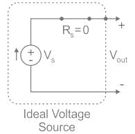
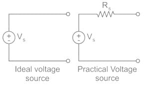
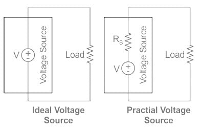
Ideal voltage source:
The ideal voltage source doesn’t consist of any load across it.
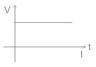
The whole input applied will be available at the output as shown:

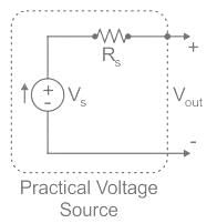
Practical voltage source:
It consists of a series of resistance that is connected to the battery and some of the voltage drops across it.


Applying the KVL we get:
Vin - I(Rs) = Vout
The output voltage, i.e. the voltage across the battery has now decreased, i.e. if we increase the value of the series resistance, the battery voltage decreases. Here consider the series resistance as load.

Test: Dependent & Independent Sources - 2 - Question 2

An ideal voltage source should have

Detailed Solution for Test: Dependent & Independent Sources - 2 - Question 2

Ideal voltage source: An ideal voltage source have zero source resistance.

Practical voltage source: A practical voltage source consists of an ideal voltage source (VS) in series with internal resistance (RS) as follows.

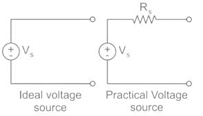
An ideal voltage source and a practical voltage source can be represented as shown in the figure.

1 Crore+ students have signed up on EduRev. Have you? Download the App
Test: Dependent & Independent Sources - 2 - Question 3

Which of the following figures is correct in representing the voltage-dependent current source ?

Detailed Solution for Test: Dependent & Independent Sources - 2 - Question 3

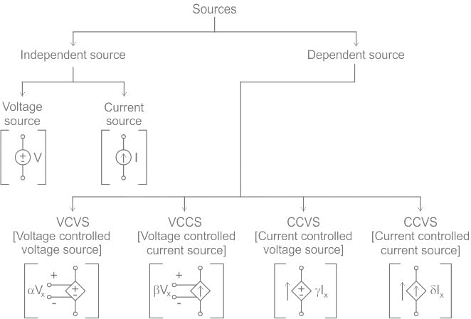
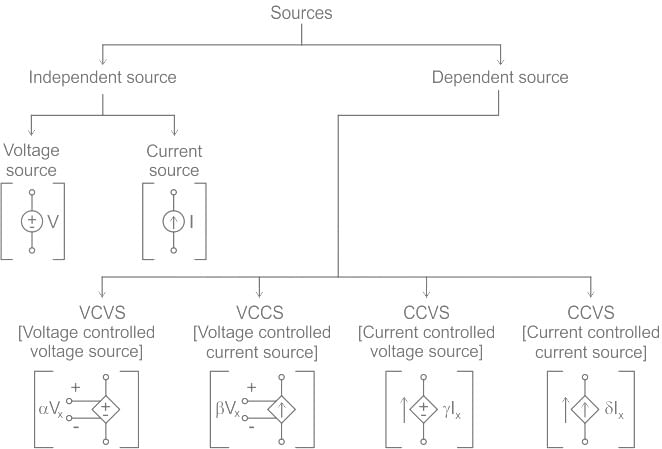
There are two kinds of voltage or current sources:

Independent Source: It is an active element that provides a specified voltage or current that is completely independent of other circuit variables.

Dependent Source: It is an active element in which the source quantity is controlled by another voltage or current in the circuit.

Test: Dependent & Independent Sources - 2 - Question 4

The internal resistances of an ideal Voltage source and an ideal current source respectively are (in ohms)

Detailed Solution for Test: Dependent & Independent Sources - 2 - Question 4

Ideal voltage source: An ideal voltage source have zero internal resistance.

Practical voltage source: A practical voltage source consists of an ideal voltage source (VS) in series with internal resistance (RS) as follows.

An ideal voltage source and a practical voltage source can be represented as shown in the figure.

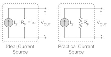
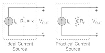
Ideal current source: An ideal current source has infinite resistance. Infinite resistance is equivalent to zero conductance. So, an ideal current source has zero conductance.

Practical current source: A practical current source is equivalent to an ideal current source in parallel with high resistance or low conductance.

Ideal and practical current sources are represented as shown in the below figure.

Test: Dependent & Independent Sources - 2 - Question 5

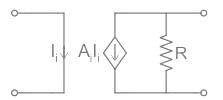
The circuit shown in the figure represents a
Detailed Solution for Test: Dependent & Independent Sources - 2 - Question 5

Concept:

There are two kinds of voltage or current sources:
Independent Source: It is an active element that provides a specified voltage or current that is completely independent of other circuit variables.
Dependent Source: It is an active element in which the source quantity is controlled by another voltage or current in the circuit.

Test: Dependent & Independent Sources - 2 - Question 6

Which of the followings is/are active element?

Detailed Solution for Test: Dependent & Independent Sources - 2 - Question 6
  • An active component is an electronic component that supplies energy to a circuit.
  • Active elements have the ability to electrically control electron flow.

Common examples of active components are:

  • Voltage sources
  • Current Sources
  • Generators
  • Transistors

The most important active elements are the voltage or current sources that generally deliver power to the circuit connected to them.

Test: Dependent & Independent Sources - 2 - Question 7

An ideal voltage source and an ideal voltmeter have internal impedances respectively:

Detailed Solution for Test: Dependent & Independent Sources - 2 - Question 7

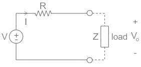
The General structure of a practical voltage source is shown below:

Writing the KVL, we get:
-V + IR + IZ = 0
V = IR + IZ
V0 = I × Z
V0 = V – IR
The output is depending on the internal resistance (R) of source.
For ideal voltage R = 0
V0 = V – I(0)
V0 = V
∴ The output is independent of the internal resistance as shown:

Voltmeter:
It is an instrument used for measuring the electric potential difference between two points in an electric circuit.
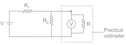
The structure of the voltmeter is shown as:


To get the correct reading of the meter the internal resistance should not get any current i.e., ideally i  = 0, R = ∞
If this is not the case, then the voltage across internal resistance will be displayed in the meter.

Conclusion:

  • Ideal voltage source internal resistance Rs = 0
  • Ideal voltmeter internal resistance Rm = ∞
Test: Dependent & Independent Sources - 2 - Question 8

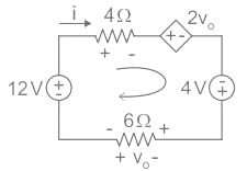
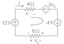
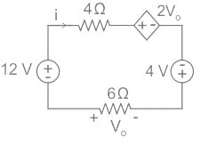
Determine 'i' in the circuit shown in Fig.
Detailed Solution for Test: Dependent & Independent Sources - 2 - Question 8

Concept:
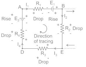
While applying KVL, the direction in which loop is to be traced is not important and following the sign convention is most important which is shown in below circuit


We can write an equation by using KVL around this closed path as,

-I1R1 + E1 – I2 R2 – I3 R3 – I4 R4 + E2 = 0 (Required KVL equation)
i.e. E1 + E = I R1 + I2R2 + I3R3 + I4R4

Explanation:

Circuit diagram:

Applying KVL in loop:

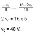
Substituting ' i ' from equation (2) into (1).

From equation 2 
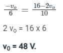
i = - vo / 6 = - 48 / 6 = - 8 A 

Test: Dependent & Independent Sources - 2 - Question 9

Find the value of 'v0' in the following circuit.
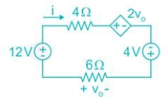
Detailed Solution for Test: Dependent & Independent Sources - 2 - Question 9

Concept:

While applying KVL, the direction in which loop is to be traced is not important and following the sign convention is most important which is shown in below circuit


We can write an equation by using KVL around this closed path as,
-I1 R1 + E1 – I2 R2 – I3 R3 – I4R4 + E2 = 0 (Required KVL equation)
i.e. E1 + E = IR1 + I2R2 + I3R3 + I4R4

Explanation:
Circuit diagram:

Applying KVL in loop:

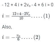
Also,

Substituting ' i ' from equation (2) into (1).

Test: Dependent & Independent Sources - 2 - Question 10

The symbol shown here is:

Detailed Solution for Test: Dependent & Independent Sources - 2 - Question 10

Concept:
Independent sources:
An independent voltage source maintains a voltage (fixed or varying with time) which is not affected by any other quantity. Similarly, an independent current source maintains a current (fixed or time-varying) which is unaffected by any other quantity.

Dependent sources:

  • Some voltage (current) sources have their voltage (current) values varying with some other variables.
  • They are called dependent (voltage or current) sources or controlled (voltage or current) sources.
  • It is represented in diamond symbol.
  • Since the control of the dependent source is achieved by a voltage or current of some other element in the circuit, and the source can be voltage or current. 
  • It follows that there are four possible types of dependent sources, namely:
  1. Voltage-controlled voltage source (VCVS)
  2. Current-controlled voltage source (CCVS)
  3. Current-controlled current source (CCCS)
  4. Voltage-controlled current source (VCCS)

Application:

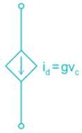
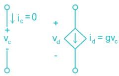
1.  

In the given circuit, the dependent source is a current source (gvc) which depends on the voltage in the other branch. Hence dependent source in the circuit is a voltage-controlled current source.

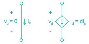
2. 

In the given circuit, the dependent source is a current source (dic) which depends on the current in the other branch. Hence dependent source in the circuit is a current-controlled current source.

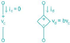
3. 

In the given circuit, the dependent source is a voltage source (bvc) which depends on the voltage in the other branch. Hence dependent source in the circuit is a voltage-controlled voltage source.

4. 

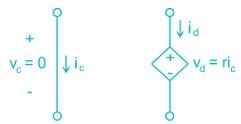
In the given circuit, the dependent source is a voltage source (ric) which depends on the current in the other branch. Hence dependent source in the circuit is a current-controlled voltage source.

Test: Dependent & Independent Sources - 2 - Question 11

Which statement is true -

Detailed Solution for Test: Dependent & Independent Sources - 2 - Question 11

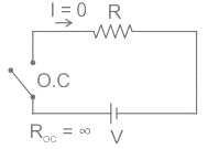
Open circuit:

  • An open circuit is the condition of a circuit in which current will not be able to flow through it even potential difference is existing.
  • And according to Ohm’s law: V = IR, if the value of current is zero then resistance will be infinite.
  • The Open circuit has broken in the continuity of supply.

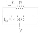
Short Circuit:

  • A short circuit is the condition of a circuit in which current will flow through the zero resistance path.
  • And according to Ohm’s law: V = IR, if the value of resistance is zero then the value of current flowing through the circuit becomes very high.

Test: Dependent & Independent Sources - 2 - Question 12

Name the circuit element maintaining a prescribed voltage across the terminals in spite of the current flowing in those terminals

Detailed Solution for Test: Dependent & Independent Sources - 2 - Question 12

Ideal Voltage Source:

  • By definition, an ideal voltage source is a two-terminal element with the property that the voltage across the terminals is specified at every instant in time. This voltage does not depend on the current through the source. That is, any current in any direction could possibly flow through the source.
  • Depending on the actual direction of the current through the source, the voltage source can either provide power or absorb it.
     

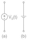
The circuit notation for an ideal voltage source is given as:

Test: Dependent & Independent Sources - 2 - Question 13

A practical current source is usually represented by

Detailed Solution for Test: Dependent & Independent Sources - 2 - Question 13

Ideal Current Source: An ideal voltage source has infinite resistance. Infinite resistance is equivalent to zero conductance. So, an ideal current source has zero conductance.

Practical Current Source: A practical current source is equivalent to an ideal current source in parallel with high resistance or low conductance.

Ideal and practical current sources are represented as shown in the below figure.

Test: Dependent & Independent Sources - 2 - Question 14

If Current in a circuit is zero ampere, it is likely that 

Detailed Solution for Test: Dependent & Independent Sources - 2 - Question 14
  • Current flowing through the open circuit is always zero. i.e. current cant't flow through a open circuit.
  • Current requires a closed path to flow through a circuit.
  • Open circuit have infinite resistance.
  • Closed or short circuited circuit have zero resistance.
  • Voltage across a circuit is always zero.
Test: Dependent & Independent Sources - 2 - Question 15

Which of following is represented in the given figure?
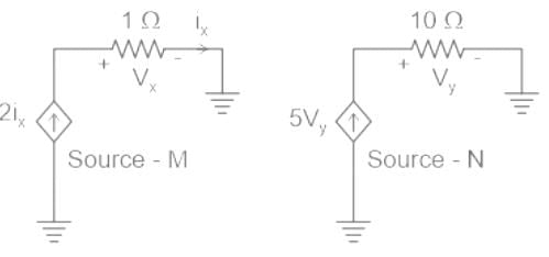
Detailed Solution for Test: Dependent & Independent Sources - 2 - Question 15

The correct answer is option 3 i.e. Source - M is a current dependent current source and Source - N is a voltage dependent current source.
Concept:

  • Current Dependent Current Source (M):
    • This type of source generates a current output that is directly proportional to the current flowing through another element in the circuit.
    • It's symbolized by a diamond shape with an arrow indicating the direction of current flow.
    • The proportionality between the output current (I_out) and the controlling current (I_ctrl) is defined by a gain factor (K). This gain factor can be positive or negative.
    • Positive gain (K > 0): The output current changes in the same direction as the controlling current (e.g., if the controlling current increases, the output current also increases).
    • Negative gain (K < 0): The output current changes in the opposite direction as the controlling current (e.g., if the controlling current increases, the output current decreases).
  • Voltage Dependent Current Source (N):
    • This type of source generates a current output that is controlled by the voltage across another element in the circuit.
    • It's also symbolized by a diamond shape with an arrow indicating the direction of current flow.
    • The relationship between the output current (I_out) and the controlling voltage (V_ctrl) depends on the specific source and can be linear or non-linear.
    • In some cases, the output current might be directly proportional to the controlling voltage (similar to a transconductance amplifier).
    • In other cases, the relationship might be more complex, involving exponential or other functions.
Information about Test: Dependent & Independent Sources - 2 Page
In this test you can find the Exam questions for Test: Dependent & Independent Sources - 2 solved & explained in the simplest way possible. Besides giving Questions and answers for Test: Dependent & Independent Sources - 2, EduRev gives you an ample number of Online tests for practice

Top Courses for Electronics and Communication Engineering (ECE)

Download as PDF

Top Courses for Electronics and Communication Engineering (ECE)