Electrical Engineering (EE) Exam  >  Electrical Engineering (EE) Tests  >  Test: Inductance - 1 - Electrical Engineering (EE) MCQ

Test: Inductance - 1 - Electrical Engineering (EE) MCQ


Test Description

10 Questions MCQ Test - Test: Inductance - 1

Test: Inductance - 1 for Electrical Engineering (EE) 2024 is part of Electrical Engineering (EE) preparation. The Test: Inductance - 1 questions and answers have been prepared according to the Electrical Engineering (EE) exam syllabus.The Test: Inductance - 1 MCQs are made for Electrical Engineering (EE) 2024 Exam. Find important definitions, questions, notes, meanings, examples, exercises, MCQs and online tests for Test: Inductance - 1 below.
Solutions of Test: Inductance - 1 questions in English are available as part of our course for Electrical Engineering (EE) & Test: Inductance - 1 solutions in Hindi for Electrical Engineering (EE) course. Download more important topics, notes, lectures and mock test series for Electrical Engineering (EE) Exam by signing up for free. Attempt Test: Inductance - 1 | 10 questions in 30 minutes | Mock test for Electrical Engineering (EE) preparation | Free important questions MCQ to study for Electrical Engineering (EE) Exam | Download free PDF with solutions
Test: Inductance - 1 - Question 1

What is the power dissipation (in W) in an ideal inductor having an inductance of 0.2 H? 

Detailed Solution for Test: Inductance - 1 - Question 1

AC through Pure Inductor:

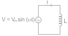
Consider a pure inductor of inductance L connected to an alternating voltage given by,

v = Vm sin ωt

An alternating current (i) flows through the inductor and sets up a changing magnetic field and it induced a back EMF (-L di/dt).

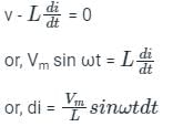
By using KVL,

Integrating on both side,

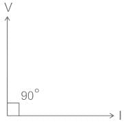
The phasor diagram can be drawn as,

From the phasor diagram, it is clear that the phase angle between voltage and current is 90°.

We know that the power factor is the cosine angle of voltage and current,

Hence, Power Factor = cos ϕ = cos 90° = 0

We know that,

Power Dissipation (P) = VIcos ϕ

Since, ϕ = 90° ⇒ cos ϕ = cos 90° = 0

Hence, Power Dissipation (P) = 0

Test: Inductance - 1 - Question 2

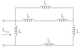
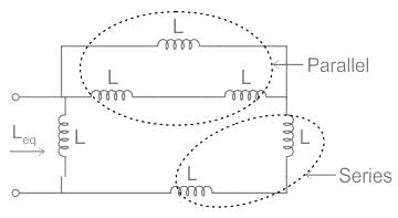
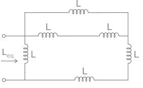
Consider the image given below. According to the image, find out the value of Leq if L is 22 mH.
Detailed Solution for Test: Inductance - 1 - Question 2

Note: Calculation for series & parallel connection of inductance is same as the resistance:

Application:

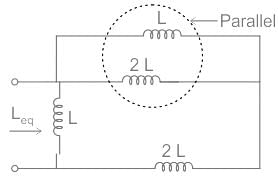
We have,

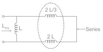
It can be drawn as,

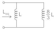
After solving it,

Leq = 16 mH

1 Crore+ students have signed up on EduRev. Have you? Download the App
Test: Inductance - 1 - Question 3

Self-induction is sometimes analogously called:

Detailed Solution for Test: Inductance - 1 - Question 3

Self induction:

  • The self inductance is defined as the property by virtue of which coil opposes any change in the current flowing through it.
  • Due to this self inductance, when the current in the coil is increased, the self induced EMF in it will oppose this increase by acting in the direction opposite to that of the applied EMF.
  • Similarly, if the current in the coil is decreased, he self induced EMF will tend to keep the current at its original value by acting in the same direction as the applied EMF.
  • Thus, any change in the current  through the coil is opposed due to its self inductance.
  • Hence, self-inductance is sometimes analogously called electrical inertia or electromagnetic inertia. 
Test: Inductance - 1 - Question 4

Two coils in differential connection have a self-inductance of 2 mH and 4 mH and mutual inductance of 0.15 mH. The equivalent inductance of the series opposing combination will be:

Detailed Solution for Test: Inductance - 1 - Question 4

Concept:

Series Aiding:

The equivalent inductance of series aiding connection is:

Leq = L1 + L2 + 2M

Series Opposing:

The equivalent inductance of series opposing connection is:

Leq = L1 + L2 – 2M

Calculation:

Given,

L1 = 2 mH

L2 = 4 mH

M = 0.15 mH

And connected with series opposing polarity.

From above concept,

Leq = L1 + L2 - 2M

Leq = 2 + 4 - 2 (0.15)

Leq = 5.7 mH

Test: Inductance - 1 - Question 5

If both the number of turns and core length of an inductive coil are doubled, then its self inductance will be

Detailed Solution for Test: Inductance - 1 - Question 5

CONCEPT:

Self-Induction

  • Whenever the electric current passing through a coil changes, the magnetic flux linked with it will also change.
  • As a result of this, in accordance with Faraday’s laws of electromagnetic induction, an emf is induced in the coil which opposes the change that causes it.
  • This phenomenon is called ‘self-induction’ and the emf induced is called back emf, current so produced in the coil is called induced current.
  • Self-inductance of a solenoid is given by –

⇒ 

Where μo = Absolute permeability, N = Number of turns, l = length of the solenoid, and A = Area of the solenoid.

Given - l2 = 2l1

N2 = 2 N1

Self-inductance of a solenoid is given by:

⇒ 

⇒ 

L2 = 2 L1​

Test: Inductance - 1 - Question 6

The energy stored in a coil with inductance L is determined as:

Detailed Solution for Test: Inductance - 1 - Question 6

Current: Rate of flow of charge is known as current. It can be expressed as

I = dq/dt

Where, q = Charge in coulomb

t = time in seconds

The energy stored by an inductor carrying a current I is given by:

Energy, E = 1/2LI2  Joule

Where, L = Inductance of the coil

Now energy stored by inductor can also be expressed as

Test: Inductance - 1 - Question 7

Inductance of a solenoid of 2500 turns wound uniformly over a length of 0.5 m cylindrical paper tube of 4 cm diameter in air medium is around:

Detailed Solution for Test: Inductance - 1 - Question 7

Given that, number of turns (N) = 2500

Diameter (d) = 4 cm

Length (l) = 0.5 m

The value of permeability in air is taken as 4π × 10-7.

Self-inductance of a solenoid is given by:

Test: Inductance - 1 - Question 8

Two coils having self-inductance of 18 H and 2 H, respectively, are magnetically coupled and the mutual inductance between them is 3 H. Find the value of coefficient of coupling.

Detailed Solution for Test: Inductance - 1 - Question 8

Concept:

Coefficient of Coupling (k):
The coefficient of coupling (k) between two coils is defined as the fraction of magnetic flux produced by the current in one coil that links the other.

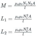
Two coils have self-inductance L1 and L2, then mutual inductance M between them then Coefficient of Coupling (k) is given by 

Where,

N1 and N2 is the number of turns in coil 1 and coil 2 respectively
A is the cross-section area
l is the length

Calculation:

Given,

L1 = 18 H

L2 = 2 H

M = 3 H

From the above concept,

Test: Inductance - 1 - Question 9

If the number of turns in a coil is doubled in the same length and area, the inductance L will

Detailed Solution for Test: Inductance - 1 - Question 9

Concept:

The inductance of a coil is given by:

N = number of turns in the coil

A = Area of the cross-section

l = length of the coil

μ = magnetic permeability of the coil

Application:

With N2 = 2 × N1, A2 = A1 and l2 = l1

∴ If the number of turns in a coil is doubled in the same length and area, the inductance L will quadruple.

Test: Inductance - 1 - Question 10

If a brass core of an inductor is replaced by an iron core, the inductance of coil:

Detailed Solution for Test: Inductance - 1 - Question 10

The inductance of an inductor is primarily determined by four factors:

  • The type of core material
  • The number of turns of wire
  • The spacing between turns of wire
  • The diameter of the coil (core)

The type of core material:

  • The core of an inductor is the material that occupies the space enclosed by the turns of the inductor.
  • The amount of current in an iron-core inductor also influences its inductance. This is because of the magnetic properties of the iron core change as the current changes.
  • The amount of inductance is determined by the amount of emf produced by a specified current change. The amount of emf depends on how much flux interacts with the conductors of the coil.
  • If all the other factors are equal, an iron-core inductor has more inductance than an air-core inductor. This is because the iron has a higher permeability i.e. it can carry more flux.
  • The brass core has more reluctance which opposes the flux compared to air core or an iron core. Therefore, the brass slug decreases inductance when it is centered in the coil.
  • Therefore, if a brass core of an inductor is replaced by an iron core, the inductance of coil increases.
Information about Test: Inductance - 1 Page
In this test you can find the Exam questions for Test: Inductance - 1 solved & explained in the simplest way possible. Besides giving Questions and answers for Test: Inductance - 1, EduRev gives you an ample number of Online tests for practice

Top Courses for Electrical Engineering (EE)

Download as PDF

Top Courses for Electrical Engineering (EE)