Electrical Engineering (EE) Exam  >  Electrical Engineering (EE) Tests  >  Test: Laplace Analysis of Networks - Electrical Engineering (EE) MCQ

Test: Laplace Analysis of Networks - Electrical Engineering (EE) MCQ


Test Description

15 Questions MCQ Test - Test: Laplace Analysis of Networks

Test: Laplace Analysis of Networks for Electrical Engineering (EE) 2024 is part of Electrical Engineering (EE) preparation. The Test: Laplace Analysis of Networks questions and answers have been prepared according to the Electrical Engineering (EE) exam syllabus.The Test: Laplace Analysis of Networks MCQs are made for Electrical Engineering (EE) 2024 Exam. Find important definitions, questions, notes, meanings, examples, exercises, MCQs and online tests for Test: Laplace Analysis of Networks below.
Solutions of Test: Laplace Analysis of Networks questions in English are available as part of our course for Electrical Engineering (EE) & Test: Laplace Analysis of Networks solutions in Hindi for Electrical Engineering (EE) course. Download more important topics, notes, lectures and mock test series for Electrical Engineering (EE) Exam by signing up for free. Attempt Test: Laplace Analysis of Networks | 15 questions in 45 minutes | Mock test for Electrical Engineering (EE) preparation | Free important questions MCQ to study for Electrical Engineering (EE) Exam | Download free PDF with solutions
Test: Laplace Analysis of Networks - Question 1

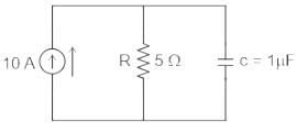
For the RC parallel circuit, determine the voltage across the capacitor using Laplace transform, assume capacitor is initially relaxed.
Detailed Solution for Test: Laplace Analysis of Networks - Question 1

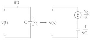
Concept:

If V0 is the initial voltage across capacitor

Calculation:

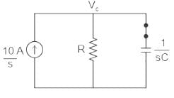
Circuit diagram at laplace domain

As capacitor was initially relaxed: V0 = 0 (Voltage source will be replaced by a short circuit)

Given;

C = 1μF

R= 5 Ω 

Use nodal analysis at node VC

⇒ VC/R + VC/(1/sC) = 10/s

⇒ VC( 1/R + sC) = 10/s

⇒ VC( 1+ sRC)/R = 10/s

⇒ VC= 10R/s( 1+ sRC)

⇒ VC= 10R/sRC( 1/RC+ s)

⇒ VC= (10/C)/s( s+ 1/RC)

⇒ VC = A/s + B/(s + 1/RC)

Determine the values of A and B using partial fraction

As=0 = (10/C)/(s + 1/RC) = (10/C)( 0 +1/RC) = 10R

Bs= -1/RC = (10/C)/s = -10R

⇒ VC = (10R)/s + (-10R)/(s + 1/RC)

Using inverse laplace transform:

⇒ VC = 10R -10Re-t/RC

⇒ VC = 10R(1 -e-t/RC)

∴  VC = 50(1 - e-t/5)

Test: Laplace Analysis of Networks - Question 2

Calculate the transfer function of a system if the response is c(t) = e-6t for t > 0. 

Given the input signal is an impulse signal.

Detailed Solution for Test: Laplace Analysis of Networks - Question 2

The ratio of Laplace transforms of output to the Laplace transform of the input assuming all inertial conditions are zero.

L[0] is Laplace transform of output

L[I] is Laplace transform of the input

Solution:

Output = e-6t

L[0] = L[e-6t]

⇒ L[0] = 1 / s+6

We have, input signal is an impulse signal.

⇒ Input = δ(t)

L[I] = 1

From above concept,

Hence, 

1 Crore+ students have signed up on EduRev. Have you? Download the App
Test: Laplace Analysis of Networks - Question 3

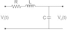
What will be the transfer function of the system shown below?
Detailed Solution for Test: Laplace Analysis of Networks - Question 3

Concept:

Transfer function:

The transfer function is defined as the ratio of the Laplace transform of the output variable to the input variable with all initial conditions zero.

TF = L[output] / L[input]| Initial conditions = 0

TF = C(s) / R(s)

The transfer function of a linear time-invariant system can also be defined as the Laplace transform of the impulse response, with all the initial conditions set to zero. 

Application:

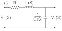
The given circuit can be drawn as in Laplace domain as shown,

For the circuit above,

Transfer Function = 

We have,

Vi (S) = I(S) (R + LS + 1/Cs)

And, Vo (S) = I(S) (1Cs)

From equation (1),

⇒ Transfer Function = 

Test: Laplace Analysis of Networks - Question 4

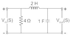
The voltage transfer function of the network shown in the figure below is
Detailed Solution for Test: Laplace Analysis of Networks - Question 4

Concept:

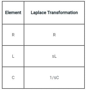
The Laplace transform resistance, inductor, and capacitance are given by:

  1. Resistance: R
  2. Inductor: sL
  3. Capacitor: 1 / sC

​Calculation:

The circuit diagram in the Laplace domain is given below:

Applying voltage division rule across capacitor:

Test: Laplace Analysis of Networks - Question 5

Which of the following is NOT one of the properties of transfer function?

Detailed Solution for Test: Laplace Analysis of Networks - Question 5

Transfer function:

The transfer function is defined as the ratio of the Laplace transform of the output variable to the input variable with all initial conditions zero.

TF = L[output] / L[input]| Initial conditions = 0

TF = C(s) / R(s)

The transfer function of a linear time-invariant system can also be defined as the Laplace transform of the impulse response, with all the initial conditions set to zero.

Properties of transfer function:

  • The transfer function is defined only for a linear time-invariant system. It is not defined for nonlinear systems.
  • The transfer function is independent of the input and output.
  • Because the transfer function of the system depends on the governing dynamic equation of the system only.
  • If the transfer function is dependent on the input means the system will come under non-linear systems, but actually, the transfer function is defined for linear systems only.
  • Transfer function analysis is not valid for the system that contains variables having initial values.
Test: Laplace Analysis of Networks - Question 6

If the step response to the input step amplitude of 1 V is given by Vo(t) = (1 - e-t / RC), the network can be represented by:

Detailed Solution for Test: Laplace Analysis of Networks - Question 6

Concept:

A transfer function is defined as the ratio of the Laplace transform of output to the Laplace transform of input when initial conditions are zero.

Where, Vo = Output voltage

V= input voltage

Calculation:

Vo(t) = (1 - e-t / RC)   ---(1)

Vi(t) = 1 V  ---(2)

Applying Laplace transform to the (1) equation:

Now taking Laplace transform of equation (2):

Vi(s) = 1 / s

Now dividing V0(s) by Vi(s) we get:

Now consider the diagram given in option(a):

Finding V0 by using voltage division rule:

Hence it gives the same transfer function as calculated in equation (4)

Hence option (a) is the correct answer.

Test: Laplace Analysis of Networks - Question 7

The transfer function of a linear system is the

Detailed Solution for Test: Laplace Analysis of Networks - Question 7

Transfer function:

  • The transfer function of a control system is defined as the ratio of the Laplace transform of the output variable to Laplace transform of the input variable assuming all initial conditions to be zero.
  • It is also defined as the Laplace transform of the impulse response.

If the input is represented by R(s) and the output is represented by C(s), then the transfer function will be:


Test: Laplace Analysis of Networks - Question 8

Transfer functions can be derived for a

Detailed Solution for Test: Laplace Analysis of Networks - Question 8

Concept:

  • Transfer Functions are  particularly useful in LTI systems for two reasons:
  • If your input is made up of a bunch of these little parts, then you can use the transfer function to find the combined output. For instance, if your input was sin(t)+sin(2t), then your output would be:

ysin(t) + sin(2t) = ysin(t) + ysin(2t) = 10sin(t) + 2sin(2t)

So,  the transfer function tells us how the system reacts to all types of inputs. This is not true for non-linear systems, so the transfer function isn't useful there.

If your input is delayed, then the output is also delayed:

ysin(t − 1) = 10sin(t - 1)

So, the transfer function is valid for time-shifted inputs. Again, for time-variant systems, this isn't true, so if your input has phase shifts, then the transfer function is useless.

To sum up: LTI systems have nice properties that let us use a simple-looking transfer function to deal with non-simple inputs. When you take away linearity and time-invariance, the transfer function doesn't give you enough information to be helpful.

Test: Laplace Analysis of Networks - Question 9

The average power consumed by the following circuit is

Vrms = 20∠ 53.13°V 

Detailed Solution for Test: Laplace Analysis of Networks - Question 9

Concept:

  • “Average power observed by Resistor” (P)
  • “Reactive power observed by Inductor OR capacitor” (Q).

Calculation:

Since we know active power OR average power observed by Inductor is zero.

Method 1:

Method 2:

Current through Resistor :

Test: Laplace Analysis of Networks - Question 10

The final value of  will be

Detailed Solution for Test: Laplace Analysis of Networks - Question 10

Concept:

1. Final value theorem:

A final value theorem allows the time domain behavior to be directly calculated by taking a limit of a frequency domain expression

The final value theorem states that the final value of a system can be calculated by

Where F(s) is the Laplace transform of the function.

For the final value theorem to be applicable system should be stable in a steady-state and for that real part of the poles should lie on the left side of s plane.

2. Initial value theorem:

It is applicable only when the number of poles of C(s) is more than the number of zeros of C(s).

Calculation:
Given that, 

Poles lies at s = 0, ±j 1

Roots lies on the imaginary axis, so it is marginally stable.

So the Final value theorem is not applicable as the system is oscillatory in nature. 

∴ The correct answer is option C 'cannot be determined'.

Test: Laplace Analysis of Networks - Question 11

Transfer function may be defined as ______

Detailed Solution for Test: Laplace Analysis of Networks - Question 11

Transfer function may be defined as the ratio of laplace transform of output to input with zero initial conditions.

Test: Laplace Analysis of Networks - Question 12

Any system is said to be stable if and only if ____________

Detailed Solution for Test: Laplace Analysis of Networks - Question 12

Any system is said to be stable if and only if it poles lies at the left of imaginary axis.

Test: Laplace Analysis of Networks - Question 13

The transfer function of a system having the input as X(s) and output as Y(s) is?

Detailed Solution for Test: Laplace Analysis of Networks - Question 13

The transfer function is defined as the s-domain ratio of the laplace transfrom of the output to the laplace transfrom of the input. The transfer function of a system having the input as X(s) and output as Y(s) is H(s) = Y(s)/X(s).

Test: Laplace Analysis of Networks - Question 14

Find the ROC of x(t) = e-2t u(t) + e-3t u(t).

Detailed Solution for Test: Laplace Analysis of Networks - Question 14

Given x(t) = e-2t u(t) + e-3t u(t)

Laplace transform, L{x(t)} = X(s)

ROC is {σ > -2}∩{σ > -3}
Hence, the ROC is σ > -2.

Test: Laplace Analysis of Networks - Question 15

Find the Laplace transform of δ(t).

Detailed Solution for Test: Laplace Analysis of Networks - Question 15

Laplace transform, L{x(t)} = X(s)

[x(t)δ(t) = x(0)δ(t)]

= 1

Information about Test: Laplace Analysis of Networks Page
In this test you can find the Exam questions for Test: Laplace Analysis of Networks solved & explained in the simplest way possible. Besides giving Questions and answers for Test: Laplace Analysis of Networks, EduRev gives you an ample number of Online tests for practice

Top Courses for Electrical Engineering (EE)

Download as PDF

Top Courses for Electrical Engineering (EE)