Electrical Engineering (EE) Exam  >  Electrical Engineering (EE) Tests  >  Test: Control Systems - 3 - Electrical Engineering (EE) MCQ

Test: Control Systems - 3 - Electrical Engineering (EE) MCQ


Test Description

15 Questions MCQ Test - Test: Control Systems - 3

Test: Control Systems - 3 for Electrical Engineering (EE) 2024 is part of Electrical Engineering (EE) preparation. The Test: Control Systems - 3 questions and answers have been prepared according to the Electrical Engineering (EE) exam syllabus.The Test: Control Systems - 3 MCQs are made for Electrical Engineering (EE) 2024 Exam. Find important definitions, questions, notes, meanings, examples, exercises, MCQs and online tests for Test: Control Systems - 3 below.
Solutions of Test: Control Systems - 3 questions in English are available as part of our course for Electrical Engineering (EE) & Test: Control Systems - 3 solutions in Hindi for Electrical Engineering (EE) course. Download more important topics, notes, lectures and mock test series for Electrical Engineering (EE) Exam by signing up for free. Attempt Test: Control Systems - 3 | 15 questions in 45 minutes | Mock test for Electrical Engineering (EE) preparation | Free important questions MCQ to study for Electrical Engineering (EE) Exam | Download free PDF with solutions
Test: Control Systems - 3 - Question 1

The phase margin of the given system G(s) = 1 / [(s + 1) 3] is:

Detailed Solution for Test: Control Systems - 3 - Question 1

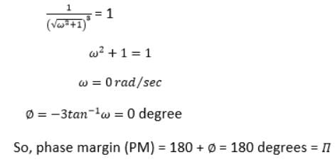
The phase margin can be calculated as: 180 + ∅

Where,

∅ is the phase of G(jω) at the gain cross over frequency.

We will first find the magnitude of the given system, as shown below:


Hence, the correct answer is an option (a).

Test: Control Systems - 3 - Question 2

The corner frequency in the Bode plot is:

Detailed Solution for Test: Control Systems - 3 - Question 2

The frequency at which the two asymptotes in the Bode plot meet is termed as corner frequency.

Hence, the correct answer is an option (d).

1 Crore+ students have signed up on EduRev. Have you? Download the App
Test: Control Systems - 3 - Question 3

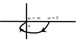
Determine the type and order of the given Nyquist plot:

Detailed Solution for Test: Control Systems - 3 - Question 3

The given plot is of the type 1/ (ST1 + 1)(ST2 + 1)

The above transfer function has order 2 and type 0.

Hence, the correct answer is an option (d).

Test: Control Systems - 3 - Question 4

The GM of a unity feedback system with the transfer function 1/ (s + 5)3 is:

Detailed Solution for Test: Control Systems - 3 - Question 4

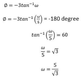
The Phase margin can be calculated as:


The gain margin (GM) = 20 log (1 / |G(s)H(s)|)

At, s = jω

We get: (GM) = 60dB

Hence, the correct answer is an option (c).

Test: Control Systems - 3 - Question 5

What will be the controller output for PD controller at t = 2s, if the error begins to change from 0 at the rate of 1.2% /s? The given parameters are Po = 50%, Kp = 4, and KD = 0.4.

Detailed Solution for Test: Control Systems - 3 - Question 5

The error the rate of 1.2% per second c neb calculated as:

e = 1.2% x 2 = 1.2/100 x 2 = 2.4%

Now, let's calculate the Pout (controller output) = 4 (2.4%+ KD x 1.2%) + Po

= 4 (2.4 / 100 + 0.4 x 1.2 /100) + 50/100

= 4 x 2.88/100 + 50/100

= 11.52/100 + 50/100

= 61.52/100

= 61.52%

Hence, the correct answer is an option (a).

Test: Control Systems - 3 - Question 6

Consider the following statements:

1. Lead compensator increases the bandwidth of the system.
2. Lag compensator suppresses steady-state performance.
3. Lead compensator improves the dynamic response and provides faster response.
4. Lag compensator acts as a low-pass filter.

Of these above statements, which of the following are true?

Detailed Solution for Test: Control Systems - 3 - Question 6

Lag compensator does not suppress steady state performance. Instead, it improves steady state performance.

Hence, the correct answer is an option (c).

Test: Control Systems - 3 - Question 7

Consider the following statements:
Phase lead:
(1) Increases the bandwidth of the system
(2) Improves the damping
(3) Reduces steady-state error
(4) Increases gain at high frequency
Which of the following statements are true?

Detailed Solution for Test: Control Systems - 3 - Question 7

Phase lead is responsible for improving the damping and reducing the system's steady-state error.

Hence, the correct answer is an option (d).

Test: Control Systems - 3 - Question 8

The sum of the Eigenvalues in the given matrix is:

Detailed Solution for Test: Control Systems - 3 - Question 8

The sum of Eigenvalue of a given matrix is generally called the trace of that matrix. The trace of a matrix is the sum of the diagonal elements of a matrix.

Hence, the correct answer is an option (d).

Test: Control Systems - 3 - Question 9

The following set of differential equations describes a linear second-order single input continuous-time system.

X1'(t) = -2X1(t) + 4X2(t)
X2'(t) = 2X1(t) - X2(t) + u(t)

Here, X1(t) and X2(t) are the state variables, and u(t) is the control variable. Check for the system, if it is:

Detailed Solution for Test: Control Systems - 3 - Question 9

We know,


Here,


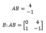
The product of matrix A and B is,


Thus, the rank of the system is 2.

The determinant of the system is non-zero. Hence, the system is controllable.

Now, we will check for stability.

SI - A = 0


The above matrix can be written in the form of an equation:

s2 + 3s -6 = 0

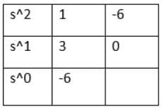
Now, we will find the roots using Routh's array table, as shown below:


There are two sign changes in the first column. Thus, the system is unstable.

Hence, the correct answer is an option (b).

Test: Control Systems - 3 - Question 10

The transfer function of a compensating network is in the form of (1 +aTs) / (1 + Ts). Find the value of 'a' if the given network is the phase-lag network.

Detailed Solution for Test: Control Systems - 3 - Question 10

The given transfer function is:

(1 +aTs) / (1 + Ts)

We will first calculate the poles and zeroes of the given transfer function.

Here,

Zero = -1/aT

Pole = -1/T

The pole in the given system is nearer to the jω axis (origin). The 0 will be far from the axis, such that the value of a < 1. It means that the value lies between 0 and 1.

Hence, the correct answer is an option (a).

Test: Control Systems - 3 - Question 11

The controller required to handle fast process load changes is:

Detailed Solution for Test: Control Systems - 3 - Question 11

The Proportional Derivative controller is preferred to handle fast process load changes.

Hence, the correct answer is an option (a).

Test: Control Systems - 3 - Question 12

The characteristic equation of the feedback control system is given as: s3 + 4s2 + (K + 5)s + K = 0

Here, K is a scalable variable parameter. In the root loci diagram of the system, the asymptotes of the root locus for large values of K meet at a point in the s-plane whose coordinate is:

Detailed Solution for Test: Control Systems - 3 - Question 12

The given equation for the feedback control system is s3 + 4s2 + (K + 5)s + K = 0

The above equation can also be written as:

s3 + 5s2 + Ks + 6s + K = 0

s3 + 5s2 + 6s + K(s + 1) = 0

s (s2 + 5s + 6) + K(s + 1) = 0

1 + K(s + 1) / [s (s2 + 5s + 6)] = 0

1 + K(s + 1) / s (s2 + 2s + 3s + 6) = 0

1 + K(s + 1) / s (s + 2)(s + 3) = 0

Now, we will calculate the value of centroid, which is equal to:

σ= / (P - Z)

Here, the number of poles and zeroes are 3 and 1.

σ= [(0 - 2 - 3) + 1] / (3 - 1)

σ=(-4)⁄2

σ=-2

Hence, the correct answer is option (b).

Test: Control Systems - 3 - Question 13

An open loop transfer function is given by G(s) = K (s + 1) / (s + 4)(s2 + 3s + 2). It has:

Detailed Solution for Test: Control Systems - 3 - Question 13

The formula to calculate a number of zeroes at infinity is P - Z. Here, P and Z are the number of poles and zeroes in a given transfer function.

We know that poles are calculated by equating the denominator to zero, and zeroes are calculated by equating the numerator to zero. So, for the above given transfer function, we get:

P = 3

Z = 1

So, the number of zeroes at infinity = 3 - 1 = 2

Hence, the correct answer is an option (c).

Test: Control Systems - 3 - Question 14

For the given closed-loop system, the ranges of the values of K for stability is:

Detailed Solution for Test: Control Systems - 3 - Question 14

The two blocks in the above diagram are in cascade. So, the equivalent block will be the product of these two blocks.

G(s) = k (s - 2) /(s +1) (s^2 + 9s + 16)

Now, H(s) = 1, as shown in the above block diagram. The characteristic equation will be: 1 + G(s) H(s)

C(s) = 1 + [k (s - 2) / (s + 1) (s^2 + 9s + 16)] = 0

= s^3 + 10s^2 + 25s + 16 + ks - 2k

= s^3 + 10s^2 + s (25 + k) + 16 - 2k

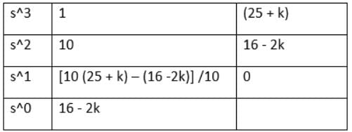
For the above equation, we need to find the roots by creating the Routh's array table.

The table is given below:


For stability,

16 - 2k > 0

16 > 2k

8 > k or k < 8

10 (25 + k) - (16 -2k) /10 > 0

250 + 10k -16 + 2k > 0

12k + 234 > 0

12k > -234

k > -19.5

From the two values of k, we can say that it lies between -19.5 < k < 8

Hence, the correct answer is an option (c).

Test: Control Systems - 3 - Question 15

If s3 + Ks2 + 5s + 10 = 0, the root of the feedback system's characteristic equation is said to be critically stable. Then, the value of K will be:

Detailed Solution for Test: Control Systems - 3 - Question 15

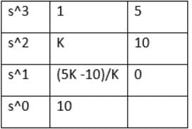
For the above equation, we need to find the roots by creating the Routh's array table. The given equation is:s3 + Ks2 + 5s + 10

The table is given below:


For the system to be critically stable, we will put (5K -10)/K = 0

5K - 10 = 0

5K = 10

K = 2

The value of K for which the system is said to be critically stable is 2.

Hence, the correct answer is an option (b).

Information about Test: Control Systems - 3 Page
In this test you can find the Exam questions for Test: Control Systems - 3 solved & explained in the simplest way possible. Besides giving Questions and answers for Test: Control Systems - 3, EduRev gives you an ample number of Online tests for practice

Top Courses for Electrical Engineering (EE)

Download as PDF

Top Courses for Electrical Engineering (EE)