Test: Problems on Initial Conditions - Electrical Engineering (EE) MCQ
10 Questions MCQ Test - Test: Problems on Initial Conditions
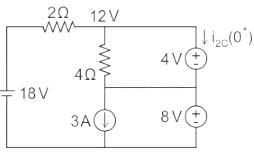
In the circuit shown below, steady state was reached when the switch ‘s’ was open. The switch was closed at t = 0. Then initial value of the current through the capacitor 2C is?
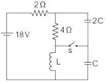

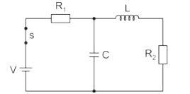
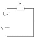
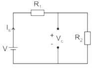
In the circuit shown in the figure, the switch S is closed at time t = 0. The supply current at t = 0+ and the capacitor voltage at t → ∞ are, respectively
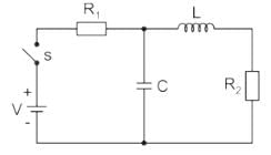

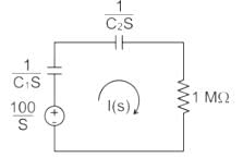
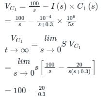
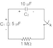
If initial voltage retained by the capacitor C1 is 100 V and C2 is zero, the switch k is closed at t = 0, the voltage drop across capacitor C1 in steady state is ________ V

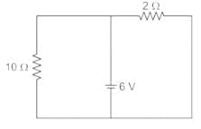
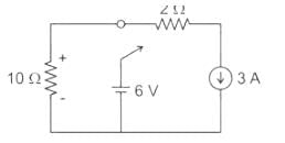
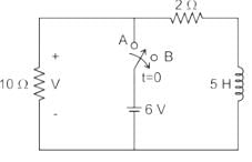
The circuit shown in figure was at steady state for t < 0 with switch at position ‘A’. The switch is thrown to position ‘B’ at time t = 0. The voltage across the 10 ohm resistor at time t = 0+ is ________V.
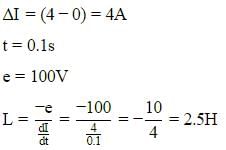
When current changes from 4A to 0A in 0.1s in an inductor the induced emf is found to be 100V, then find the value of self-inductance is :
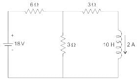
For the circuit shown in the figure, the value of  is _____ (in A/s)
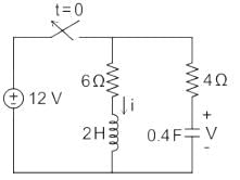
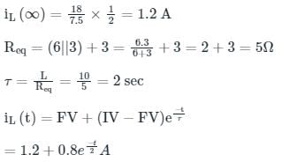
In the circuit shown in the figure, the switch s open for a long time. It is closed at t=0 For t>0 the current flowing through the inductor will be given by

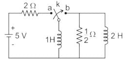
The network shown in the figure given below reaches a steady state with the switch K in position a. At t = 0, the switch is moved from a to b by a make-before-break mechanism. Assume the initial current in 2 H inductors as zero. What is the current in 1 H inductor at t = 0+and t = ∞, respectively?
Find i(0+) and V (2 m sec) for the circuit shown below.
In Reciprocity Theorem, which of the following ratios is considered?


