Electrical Engineering (EE) Exam  >  Electrical Engineering (EE) Tests  >  Test: Combinational Logic Circuits - Electrical Engineering (EE) MCQ

Test: Combinational Logic Circuits - Electrical Engineering (EE) MCQ


Test Description

10 Questions MCQ Test - Test: Combinational Logic Circuits

Test: Combinational Logic Circuits for Electrical Engineering (EE) 2024 is part of Electrical Engineering (EE) preparation. The Test: Combinational Logic Circuits questions and answers have been prepared according to the Electrical Engineering (EE) exam syllabus.The Test: Combinational Logic Circuits MCQs are made for Electrical Engineering (EE) 2024 Exam. Find important definitions, questions, notes, meanings, examples, exercises, MCQs and online tests for Test: Combinational Logic Circuits below.
Solutions of Test: Combinational Logic Circuits questions in English are available as part of our course for Electrical Engineering (EE) & Test: Combinational Logic Circuits solutions in Hindi for Electrical Engineering (EE) course. Download more important topics, notes, lectures and mock test series for Electrical Engineering (EE) Exam by signing up for free. Attempt Test: Combinational Logic Circuits | 10 questions in 30 minutes | Mock test for Electrical Engineering (EE) preparation | Free important questions MCQ to study for Electrical Engineering (EE) Exam | Download free PDF with solutions
Test: Combinational Logic Circuits - Question 1

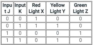
A combinational logic circuit for traffic control is designed. ___________ GATE can only be used to implement the designed control circuit without any additional GATES.

Detailed Solution for Test: Combinational Logic Circuits - Question 1

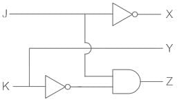
The logic gate for traffic control is:

For red light
Output X = NOT (J)

For yellow light
Output Y = K

For green light:
Output Z = J AND (NOT K)

Combined Circuit is given as,

Now, all the gates can be formed from NAND gate, as it is a universal gate. 
NAND gate will be the correct answer. 

Test: Combinational Logic Circuits - Question 2

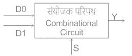
In the figure shown, D0 and D1 are digital inputs, S is a control input and Y is the output. When S = 0, then Y = D0. When S = 1, then Y = D1. The given combinational circuit is

Detailed Solution for Test: Combinational Logic Circuits - Question 2

Multiplexers:

  • A multiplexer is a combinational circuit.
  • A multiplexer is Many to one data selector.
  • A multiplexer selects one of the many data available at its input depending on the bits on the select line.
  • For 2n inputs, there are n select lines that determine, which input is to be connected to the output.

A 2-input multiplexer is as shown below.

Output, Y = D0S̅ + D1S

1 Crore+ students have signed up on EduRev. Have you? Download the App
Test: Combinational Logic Circuits - Question 3

_______ are an example of a combinational circuit.

Detailed Solution for Test: Combinational Logic Circuits - Question 3

Combinational Logic circuits:
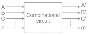
Combinational Logic circuits are circuits for which the present output depends only on the present input, i.e. there is no memory element to store the past output.
A combinational circuit can have ‘n’ number of inputs and ‘m’ number of outputs as shown:

Combinational circuits are:

  • Multiplexer/Demultiplexer
  • Encoder/Decoder
  • Adders
  • Subtractors
  • Code Converters

Multiplexers:

  • A multiplexer is Many to one data selector.
  • A multiplexer selects one of the many data available at its input depending on the bits on the select line.
  • For 2m inputs, there are m select lines that determine which input is to be connected to the output.
Test: Combinational Logic Circuits - Question 4

Any combinational circuit can be designed using only

Detailed Solution for Test: Combinational Logic Circuits - Question 4

Concept:
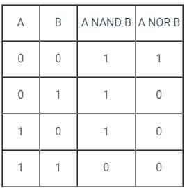
A universal gate is the one with which any other Boolean function can be implemented without the need of other gates.
Two universal gates are NAND and NOR.
NAND:
In this gate, output of logic gate is false only when both the inputs are true. It is the complement of AND gate.
NOR gate: Output of this logic gate is true when both inputs are false.
Truth Table:

Test: Combinational Logic Circuits - Question 5

Half adder is also known as

Detailed Solution for Test: Combinational Logic Circuits - Question 5

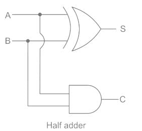
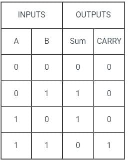
  • A half adder is also known as XOR gate because XOR is applied to both inputs to produce sum
  • Half adder can add only two bits (A and B) and has nothing to do with the carry
  • If the input to a half adder has a carry, then it will neglect it and adds only the A and B bits
  • That means the binary addition process is not complete and that's why it is called a half adder

Sum (S) = A⊕B, Carry = A.B

Test: Combinational Logic Circuits - Question 6

Number of 2 × 1 Multiplexers are required to implement 64 × 1 Multiplexers

Detailed Solution for Test: Combinational Logic Circuits - Question 6

A 64 × 1 multiplexer has 64 inputs so if we use 2 × 1 multiplexers 32 are needed in the first stage for 64 inputs, the output of these 32 multiplexers are connected to inputs of 16 multiplexers in the second stage.
Similarly, in third stage, 8 (2 × 1) multiplexers are used, in fourth stage 4 are used and finally 2 (2 × 1) multiplexers in the fifth stage, 1 in the sixth stage.
Total 2 × 1 multiplexers needed are 32 + 16 + 8 + 4 + 2 + 1 = 63.

Test: Combinational Logic Circuits - Question 7

The biggest advantage of ECL is:

Detailed Solution for Test: Combinational Logic Circuits - Question 7

ECL (Emitter Coupled Logic):

  • It is fast then all logic family and very high speed in ECL transistor use in differential amplifier configuration
  • When a transistor is operated in a saturation condition, due to the charge stored in the collector and base regions, it turns ON or OFF slowly. This drawback has been eliminated in ECL by operation the transistor only in the active or off region.
Test: Combinational Logic Circuits - Question 8

In a 1 to 4 De-multiplexer, how many select input lines are required?

Detailed Solution for Test: Combinational Logic Circuits - Question 8

DEMUX:
A demultiplexer (or demux) is a device that takes a single input line and routes it to one of several digital output lines.
It consists of 2n outputs and has n selection lines, which are used to select which output line to send the input. It is also called as a data distributor.

Test: Combinational Logic Circuits - Question 9

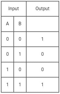
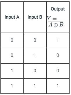
Identify the gate from the truth table

Detailed Solution for Test: Combinational Logic Circuits - Question 9

XNOR Gate:
Symbol:


Truth Table:


Output Equation: 
Key Points: 
1) If B is always Low, the output is the inverted value of the other input A, i.e. A̅.
2) The output is low when both the inputs are different.
3) The output is high when both the inputs are the same.
4) XNOR gate produces an output only when the two inputs are the same.

Test: Combinational Logic Circuits - Question 10

What determines the output from the combinational logic circuit in Digital Electronics?

Detailed Solution for Test: Combinational Logic Circuits - Question 10

The output in a combinational circuit depends on the mixture of input signals present at that moment. It is not determined by the past conditions. The output in a synchronous circuit depends on the mixture of input signals present at that moment and also the past conditions.

Information about Test: Combinational Logic Circuits Page
In this test you can find the Exam questions for Test: Combinational Logic Circuits solved & explained in the simplest way possible. Besides giving Questions and answers for Test: Combinational Logic Circuits, EduRev gives you an ample number of Online tests for practice

Top Courses for Electrical Engineering (EE)

Download as PDF

Top Courses for Electrical Engineering (EE)