Electrical Engineering (EE) Exam  >  Electrical Engineering (EE) Tests  >  Test: S-R Latch - Electrical Engineering (EE) MCQ

Test: S-R Latch - Electrical Engineering (EE) MCQ


Test Description

15 Questions MCQ Test - Test: S-R Latch

Test: S-R Latch for Electrical Engineering (EE) 2025 is part of Electrical Engineering (EE) preparation. The Test: S-R Latch questions and answers have been prepared according to the Electrical Engineering (EE) exam syllabus.The Test: S-R Latch MCQs are made for Electrical Engineering (EE) 2025 Exam. Find important definitions, questions, notes, meanings, examples, exercises, MCQs and online tests for Test: S-R Latch below.
Solutions of Test: S-R Latch questions in English are available as part of our course for Electrical Engineering (EE) & Test: S-R Latch solutions in Hindi for Electrical Engineering (EE) course. Download more important topics, notes, lectures and mock test series for Electrical Engineering (EE) Exam by signing up for free. Attempt Test: S-R Latch | 15 questions in 30 minutes | Mock test for Electrical Engineering (EE) preparation | Free important questions MCQ to study for Electrical Engineering (EE) Exam | Download free PDF with solutions
Test: S-R Latch - Question 1

When both the inputs of a latch are high, the output is unpredictable. What is this condition called?

Detailed Solution for Test: S-R Latch - Question 1

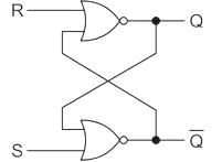
SR Latch:

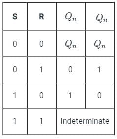
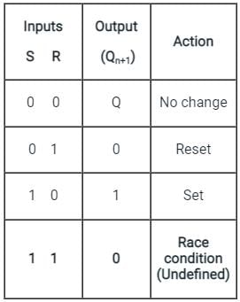
The truth table for SR latch is:

From the above table, when both the inputs of a latch are high, The out is indeterminate.

Test: S-R Latch - Question 2

Which property is NOT considered in latches?

Detailed Solution for Test: S-R Latch - Question 2

(i) Latches are level-triggered (outputs can change as soon as the inputs changes)  
(ii) Flip-Flop is edge-triggered (only changes state when a control signal goes from high to low or low to high).
(iii) Edge triggering is a type of triggering that allows a circuit to become active at the positive edge or the negative edge of the clock signal.
(iv) Level triggering is a type of triggering that allows a circuit to become active when the clock pulse is on a particular level.

Test: S-R Latch - Question 3

Which of the following can be used for debouncing a switch ?

Detailed Solution for Test: S-R Latch - Question 3
  • Switch bounce or contact bounce or even called chatter is a common problem associated with mechanical switches and relays.
  • Switch bouncing is not a major problem when we deal with the power circuits, but it causes problems while we are dealing with the logic and digital circuits.
  •  Hence, to remove the bouncing from the circuit Switch Debouncing Circuit is used.
  • The hardware debouncing technique uses an S-R latch to avoid bounces in the circuit along with the pull-up resistors. 
  • S-R circuit is the most effective of all debouncing approaches
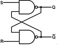
  • The figure below is a simple debouncing circuit that is often used.

SR Latch:

  • In an S-R latch, activation of the S input sets the circuit, while activation of the R input resets the circuit.
  • If both S and R inputs are activated simultaneously, the circuit will be in an invalid condition.

Application:

  • Latches are used to keep the conditions of the bits to encode binary numbers.
  • Latches are single-bit storage elements that are widely used in computing as well as data storage.
  • Latches are used in the circuits like power gating & clock as a storage device.
Test: S-R Latch - Question 4

______ is commonly used to interface output devices.

Detailed Solution for Test: S-R Latch - Question 4

Latches are memory devices and can store one bit of data for as long as the device is powered.

As the name suggests, latches are used to "latch onto" information and hold it in place.

Latches are very similar to flip-flops, but are not synchronous devices, and do not operate on clock edges as flip-flops do.

The reason for using the latch in an output port is simple, we do not want to lose the result of any operation.

So, in order to not lose it, we use a latch, so that it holds the information as long as new information is overwritten onto it.

An 8-bit latch can be used to interface the output of a microprocessor to other devices.

The 74LS373 octal latch and the 74LS374 octal D flip-flop are popular microprocessor interface chips.

Note:

Tristate buffer is commonly used to interface input devices.

Test: S-R Latch - Question 5

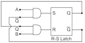
The two inputs A and B are connected to a NOR based R-S latch, via two AND gates as shown in the figure. If A = 1 and B = 0, the output QQ̅ is
Detailed Solution for Test: S-R Latch - Question 5

From the given diagram,

S = AQ̅, R = QB

Given that, A = 1, B = 0

S = Q̅, R = 0

The truth table of the S-R latch is:

Let Q = 0,

S = Q̅ = 1, R = 0 ⇒ Qn + 1 = 1

Let Q = 1,

S = Q̅ = 0, R = 0 ⇒ Qn + 1 = 1

In both the cases, Qn + 1 n + 1 = 10

Test: S-R Latch - Question 6

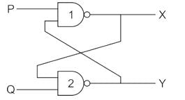
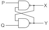
In the latch circuit shown, the NAND gates have non-zero, but unequal propagation delays. The present input conditions is: P = Q = ‘0’. If the input conditions is changed simultaneously to P = Q = ‘1’, the outputs X and Y are
Detailed Solution for Test: S-R Latch - Question 6

Let as assume tpd 1 < tpd 2

x changes state first then y changes

1st output of X (P = 1, y = 0) ⇒ X1 = 1

Next output of Y (Q = 1, X1 = 1) ⇒ Y1 = 0

2nd output of X (P = 1, y1 = 0) ⇒ 1

Hence output x = 1 y = 0 (if tpd1 < tpd2)

& Output X = 0 Y = 1 (if tpd2 < tpd1)

Test: S-R Latch - Question 7

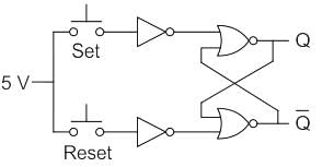
An SR latch is implemented using TTL gates as shown in the figure. The set and reset pulse inputs are provided using the push-button switches. It is observed that the circuit fails to work as desired. The SR latch can be made functional by changing
Detailed Solution for Test: S-R Latch - Question 7

Concept:

  • In the TTL logic gate, open-end or floating end are considered as logic-1.
  • For the circuit to work as an S & R latch, S & R should act as logic-0 as well as logic- 1 on requirement.

Analysis:

  • If we connect set which is equal to 5 volts, then it will be considered as logic-1.
  • If we do not connect 5 Volts to set switch i.e. if we make set switch ‘open’ then it will again be considered as a logic -1, because it is a TTL gate.
  • So we have to replace 5 V supply with 0 Volts by connecting it to ground. So logic-0 is also possible for switch ‘set’ & ‘reset’.

Hence for the above circuit to work as an SR latch, 5-volt battery should connect to ground.

Hence option -4 is Correct.

Test: S-R Latch - Question 8

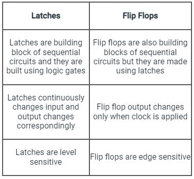
Which of the following is true?

Detailed Solution for Test: S-R Latch - Question 8

The difference between latches and flip flops is shown

Test: S-R Latch - Question 9

In S-R latch, when the SET input is made high, output Q becomes:

Detailed Solution for Test: S-R Latch - Question 9

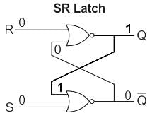
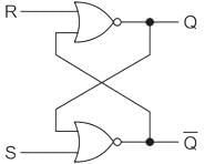
An unclocked R-S flip flop using NOR gates is as shown:

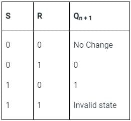
The truth table for the circuit is shown:

Test: S-R Latch - Question 10

The first step of the analysis procedure of SR latch is to ___________

Detailed Solution for Test: S-R Latch - Question 10

All flip flops have at least one output labeled Q (i.e. inverted). This is so because the flip flops have inverting gates inside them, hence in order to have both Q and Q complement available, we have atleast one output labelled.

Test: S-R Latch - Question 11

When both inputs of SR latches are high, the latch goes ___________

Detailed Solution for Test: S-R Latch - Question 11

When both gates are identical and this is “metastable”, and the device will be in an undefined state for an indefinite period.

Test: S-R Latch - Question 12

When a high is applied to the Set line of an SR latch, then ___________

Detailed Solution for Test: S-R Latch - Question 12

S input of an SR latch is directly connected to the output Q. So when a high is applied Q output goes high and Q’ low.

Test: S-R Latch - Question 13

The full form of SR is ___________

Detailed Solution for Test: S-R Latch - Question 13

The full form of SR is set/reset. It is a type of latch having two stable states.

Test: S-R Latch - Question 14

The outputs of SR latch are ___________

Detailed Solution for Test: S-R Latch - Question 14

SR or Set-Reset latch is the simplest type of bistable multivibrator having two stable states. The inputs of SR latch are s and r while outputs are q and q’. It is clear from the diagram:
.

Test: S-R Latch - Question 15

When both inputs of SR latches are low, the latch ___________

Detailed Solution for Test: S-R Latch - Question 15

When both inputs of SR latches are low, the latch remains in it’s present state. There is no change in output.

Information about Test: S-R Latch Page
In this test you can find the Exam questions for Test: S-R Latch solved & explained in the simplest way possible. Besides giving Questions and answers for Test: S-R Latch, EduRev gives you an ample number of Online tests for practice
Download as PDF