Electrical Engineering (EE) Exam  >  Electrical Engineering (EE) Tests  >  Test: Demultiplexers - 2 - Electrical Engineering (EE) MCQ

Test: Demultiplexers - 2 - Electrical Engineering (EE) MCQ


Test Description

5 Questions MCQ Test - Test: Demultiplexers - 2

Test: Demultiplexers - 2 for Electrical Engineering (EE) 2024 is part of Electrical Engineering (EE) preparation. The Test: Demultiplexers - 2 questions and answers have been prepared according to the Electrical Engineering (EE) exam syllabus.The Test: Demultiplexers - 2 MCQs are made for Electrical Engineering (EE) 2024 Exam. Find important definitions, questions, notes, meanings, examples, exercises, MCQs and online tests for Test: Demultiplexers - 2 below.
Solutions of Test: Demultiplexers - 2 questions in English are available as part of our course for Electrical Engineering (EE) & Test: Demultiplexers - 2 solutions in Hindi for Electrical Engineering (EE) course. Download more important topics, notes, lectures and mock test series for Electrical Engineering (EE) Exam by signing up for free. Attempt Test: Demultiplexers - 2 | 5 questions in 15 minutes | Mock test for Electrical Engineering (EE) preparation | Free important questions MCQ to study for Electrical Engineering (EE) Exam | Download free PDF with solutions
Test: Demultiplexers - 2 - Question 1

Which of the following statements about the demultiplexers is INCORRECT ?

Detailed Solution for Test: Demultiplexers - 2 - Question 1

Concept:
A demultiplexer is a circuit that can distribute and deliver multiple outputs from a single input. (option 2 is the correct statement)
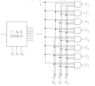
A 1-line to 8-line demultiplexer consists of 3 selection lines, eight and gates, all of which are connected to a single input data line. (option 1 is the correct statement)​

From the above figure, demultiplexer takes one input data source and selectively distributes it to 1-of-N output channels just like a multi-position switch. (option 4 is the correct statement) 
It is not used as anti-clock demultiplexers in synchronous data transmission systems in the receivers and security monitoring systems etc. (option 3 is an incorrect statement)

Test: Demultiplexers - 2 - Question 2

Which of the following circuits can be used as a series to parallel converter?

Detailed Solution for Test: Demultiplexers - 2 - Question 2

De-multiplexer:

  • The demultiplexer is a combinational logic circuit designed to switch one common input line to one of several separate output lines.
  • The data distributor, known as a Demultiplexer or “Demux”, works in just the opposite way to that of the Multiplexer.
  • The demultiplexer takes one single input data line and then switches it to any one of a number of individual output lines one at a time.

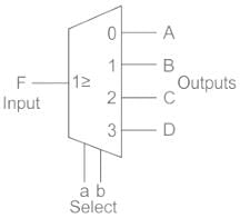
The block diagram is as shown:

Application:
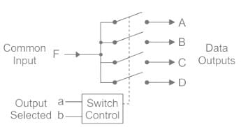
The demultiplexer converts a serial data signal at the input to parallel data at its output lines as shown below.

The function of the Demultiplexer is to switch one common data input line to any one of the 4 output data lines A to D.
Important:
Multiplexer:

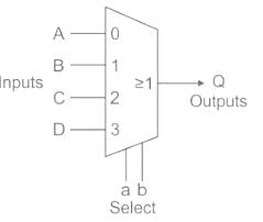
The multiplexer is a combinational logic circuit designed to switch one of several input lines to a single common output line.

  • The multiplexer or “MUX” is a combinational logic circuit designed to switch one of several input lines through a single common output line by the application of a control signal.
  • Multiplexers operate like very fast acting multiple position rotary switches connecting or controlling multiple input lines called “channels” one at a time to the output.
  • Multiplexers are used to convert parallel to serial data.
1 Crore+ students have signed up on EduRev. Have you? Download the App
Test: Demultiplexers - 2 - Question 3

In a 1 to 4 De-multiplexer, how many select input lines are required?

Detailed Solution for Test: Demultiplexers - 2 - Question 3

DEMUX:
A demultiplexer (or demux) is a device that takes a single input line and routes it to one of several digital output lines.
It consists of 2n outputs and has n selection lines, which are used to select which output line to send the input. It is also called as a data distributor.

Test: Demultiplexers - 2 - Question 4

The IC 74LS138 is a ____.

Detailed Solution for Test: Demultiplexers - 2 - Question 4
  • The IC 74LS138 is a 3 to 8 line decoder integrated circuit from the 74xx family. 
  • The main function of this IC is to decode otherwise demultiplex the applications.
  • The decoder 74LS138 IC uses advanced technology like silicon (Si) gate TTL technology.
  • 74LS138 IC has 3 binary select inputs like A, B & C. If the IC is activated, then these input pins will decide which of the 8 usually HIGH outputs will go LOW.
  • As this IC includes three enable pins (where two pins are active low and one is active high) the necessity of outside gates is not there. 
  • These are suitable for applications like memory address decoding, data routing, etc. 
Test: Demultiplexers - 2 - Question 5

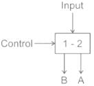
Name the following figure.

Detailed Solution for Test: Demultiplexers - 2 - Question 5

Multiplexer: Multiplexer is a device that has multiple inputs and single line output.
De-multiplexer: De-multiplexer is a device that has a signal inputs line and multiple line outputs.
The given figure has one input and two outputs. Hence it is De-multiplexer.

Combinational circuit:

  • Combinational and sequential circuits are the digital circuits made using logic gates
  • Present output depends on the present input only
  • No feedback is present
  • No memory is present

Encoder: Encoder is used to converter other codes to binary

Information about Test: Demultiplexers - 2 Page
In this test you can find the Exam questions for Test: Demultiplexers - 2 solved & explained in the simplest way possible. Besides giving Questions and answers for Test: Demultiplexers - 2, EduRev gives you an ample number of Online tests for practice

Top Courses for Electrical Engineering (EE)

Download as PDF

Top Courses for Electrical Engineering (EE)