Electrical Engineering (EE) Exam  >  Electrical Engineering (EE) Tests  >  Test: Measurement of Low Resistance - Electrical Engineering (EE) MCQ

Test: Measurement of Low Resistance - Electrical Engineering (EE) MCQ


Test Description

10 Questions MCQ Test - Test: Measurement of Low Resistance

Test: Measurement of Low Resistance for Electrical Engineering (EE) 2024 is part of Electrical Engineering (EE) preparation. The Test: Measurement of Low Resistance questions and answers have been prepared according to the Electrical Engineering (EE) exam syllabus.The Test: Measurement of Low Resistance MCQs are made for Electrical Engineering (EE) 2024 Exam. Find important definitions, questions, notes, meanings, examples, exercises, MCQs and online tests for Test: Measurement of Low Resistance below.
Solutions of Test: Measurement of Low Resistance questions in English are available as part of our course for Electrical Engineering (EE) & Test: Measurement of Low Resistance solutions in Hindi for Electrical Engineering (EE) course. Download more important topics, notes, lectures and mock test series for Electrical Engineering (EE) Exam by signing up for free. Attempt Test: Measurement of Low Resistance | 10 questions in 30 minutes | Mock test for Electrical Engineering (EE) preparation | Free important questions MCQ to study for Electrical Engineering (EE) Exam | Download free PDF with solutions
Test: Measurement of Low Resistance - Question 1

The bridge used for the measurement of the value of the capacitance is

Detailed Solution for Test: Measurement of Low Resistance - Question 1

Schering Bridge:

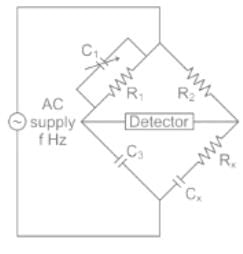
Schering bridge is a type of AC bridge that is used to measure the dissipation factor (dielectric loss) or phase angle and capacitance.

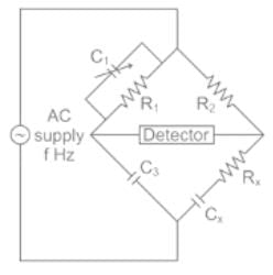
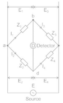
The circuit of the Schering bridge is shown below:


When the bridge is in the balanced condition, zero current passes through the detector, which shows that the potential across the detector is zero.

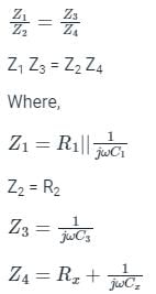
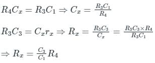
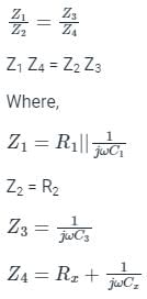
At balance condition:


Test: Measurement of Low Resistance - Question 2

In a Schering bridge, the dial of the variable capacitor is calibrated directly in terms of the dissipation factor of the unknown arm. At 50 Hz frequency, the value of the dissipation factor of the unknown capacitor was found to be D. What would be the value of the dissipation factor at 60 Hz

Detailed Solution for Test: Measurement of Low Resistance - Question 2

Concept:

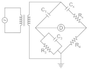
Schering bridge:

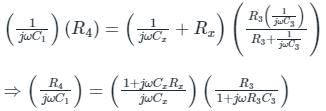
At bridge balance condition,


⇒ R4Cx (1 + jωR3C3) = R3C1 (1 + jω Cx Rx)

By comparing both sides

Dissipation factor = ωCxRx = ωR3C= 2πf R3C3

Dissipation factor α frequency(f) --------(1)

Calculation:

Given:

Dissipation factor D at frequency 50Hz

Let Dissipation factor x at frequency 60Hz

From equation 1:
f1/f2 = D/z
x = 6/5 D

1 Crore+ students have signed up on EduRev. Have you? Download the App
Test: Measurement of Low Resistance - Question 3

Dissipation factor of a capacitor can be measured with:

Detailed Solution for Test: Measurement of Low Resistance - Question 3

Dissipation factor:

The dissipation factor is defined as the value of the tendency of the dielectric material to absorb some of the energy when the AC signal is applied.

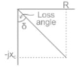
In a series RC circuit, δ refers to the angle between the series combination of R, C and the voltage across the capacitance C.

‘δ’ is also known as the loss angle

Therefore, the Dissipation factor is defined as the tangent of the loss angle.

Dissipation factor = tan δ

Schering bridge is used to measure the dissipation factor.

Test: Measurement of Low Resistance - Question 4

Which type of the bridge circuit among the following is used for measurement of capacitance?

Detailed Solution for Test: Measurement of Low Resistance - Question 4

Schering Bridge:

Schering bridge is a type of AC bridge that is used to measure the dissipation factor (dielectric loss) or phase angle and capacitance.

The circuit of the Schering bridge is shown below:


When the bridge is in the balanced condition, zero current passes through the detector, which shows that the potential across the detector is zero.

At balance condition:
=

Test: Measurement of Low Resistance - Question 5

The Schering bridge. one of the most important AC bridge
(A) It is used for capacitance measurement
(B) It is used for phase angle measurement
(C) It is used for inductance measurement
(D) It is used for resistance measurement
(E) It is used for torque measurement
Choose the correct answer from the options given below:

Detailed Solution for Test: Measurement of Low Resistance - Question 5

Schering Bridge:

Schering bridge is a type of AC bridge that is used to measure the dissipation factor (dielectric loss) or phase angle and capacitance.

The circuit of the Schering bridge is shown below:


When the bridge is in the balanced condition, zero current passes through the detector, which shows that the potential across the detector is zero.

At balance condition:


Test: Measurement of Low Resistance - Question 6

The bridge circuit shown can be used to measure unknown lossy capacitor Cx with resistance Rx. At balance:
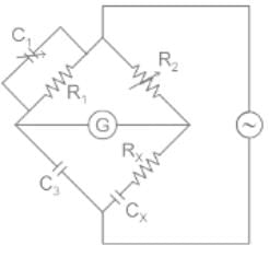
Detailed Solution for Test: Measurement of Low Resistance - Question 6

Concept:

1. The magnitude of impedances satisfy the relationship, Z1Z4 = Z2Z3

2. The phase angles of impedances satisfy the relationship, ∠θ1 + ∠θ4 = ∠θ2 + ∠θ3

These two are independent conditions for balance and both of them must be satisfied for the bridge to be balanced.

Calculation:

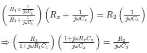
At bridge balance condition,

⇒ R1C3 (1 + jωRxCx) = R2Cx (1 + jωR1C1)
⇒ R1C3 + jωR1RxC3Cx = R2Cx + jωR1R2C1Cx
By equating the real parts on both the sides, we get

 
By equating the imaginary parts on both the sides, we get

Test: Measurement of Low Resistance - Question 7

Which of the following is used to eliminate the effect of earth capacitances?

Detailed Solution for Test: Measurement of Low Resistance - Question 7

Wagner's Earthing Device:

  • The Wagner earthing device is used for removing the effect of earth capacitances.
  • At high frequency, stray capacitance is induced between the bridge elements, ground, and between the arms of the bridge.
  • This stray element causes an error in the measurement.
  • It is a type of voltage divider circuit used to reduce the error which occurs because of stray capacitance.
  • The Wagner Earth device provides high accuracy to the bridge.

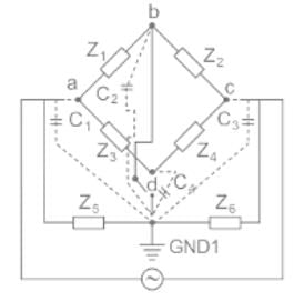
Circuit diagram for Wagner’s earthing device:


Where,

Z1 Z2 Z3 Z4 is the impedance arm of the bridge.

Z5 and Z6 are the two variable impedances of the Wagner Earth Device

C1, C2 C3, and C4 are the stray capacitances of the bridge

D is the detector

a, b, c, d, and GND1 are nodes of the bridge

In Wagner’s earthing device is adjusted such that b, d, and GND1 have equal potential

At the balanced condition,

The capacitance C1, C2, C3, C4 all are eliminated from the bridge circuit along with the impedances Z5 and Z6.

Test: Measurement of Low Resistance - Question 8

The bridge used to measure the dielectric loss of an insulator is

Detailed Solution for Test: Measurement of Low Resistance - Question 8

Test: Measurement of Low Resistance - Question 9

Which is not a source of error in the measurement of low resistance?

Detailed Solution for Test: Measurement of Low Resistance - Question 9

As the current flowing through a low resistance circuit is low, the voltage drop across the terminals due to contact and lead resistances is negligible. Thermal e.m.f occurs in a circuit when its temperature increases due to high current flow.

Test: Measurement of Low Resistance - Question 10

Low resistance refers to _________

Detailed Solution for Test: Measurement of Low Resistance - Question 10

Low resistance refers to resistance of the order of 1ῼ or less than that. Medium resistances range from above 1ῼ to a few kῼ. Any resistance value greater than a few kῼ is known as high resistance.

Information about Test: Measurement of Low Resistance Page
In this test you can find the Exam questions for Test: Measurement of Low Resistance solved & explained in the simplest way possible. Besides giving Questions and answers for Test: Measurement of Low Resistance, EduRev gives you an ample number of Online tests for practice

Top Courses for Electrical Engineering (EE)

Download as PDF

Top Courses for Electrical Engineering (EE)