Electrical Engineering (EE) Exam  >  Electrical Engineering (EE) Test  >  Analog and Digital Electronics  >  Test: Clipper & Clamper: Diode Circuits - Electrical Engineering (EE) MCQ

Clipper & Clamper: Diode Circuits - GATE EE Analog and Digital Electronics


MCQ Practice Test & Solutions: Test: Clipper & Clamper: Diode Circuits (10 Questions)

You can prepare effectively for Electrical Engineering (EE) Analog and Digital Electronics with this dedicated MCQ Practice Test (available with solutions) on the important topic of "Test: Clipper & Clamper: Diode Circuits". These 10 questions have been designed by the experts with the latest curriculum of Electrical Engineering (EE) 2026, to help you master the concept.

Test Highlights:

  • - Format: Multiple Choice Questions (MCQ)
  • - Duration: 30 minutes
  • - Number of Questions: 10

Sign up on EduRev for free to attempt this test and track your preparation progress.

Test: Clipper & Clamper: Diode Circuits - Question 1

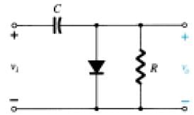
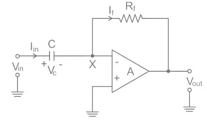
For a sinusoidal input of 20 Vpeak to the given circuit, what is the peak value of the output waveform?

Detailed Solution: Question 1

In the given circuit, the output becomes zero for vi less than -5 V. Hence, the peak value of the output is 25 V owing to the additive effect of V for vi.

Test: Clipper & Clamper: Diode Circuits - Question 2

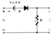
For a sinusoidal input of 20 Vpeak to the given circuit, what is the minimum value of the output waveform?

Detailed Solution: Question 2

The given circuit is a clipper that cuts off a part of the negative cycle of the input sinusoid i.e. the output becomes zero for a certain region of the input waveform. Hence, the minimum value is 0 V.

Test: Clipper & Clamper: Diode Circuits - Question 3

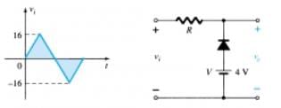
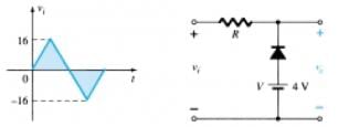
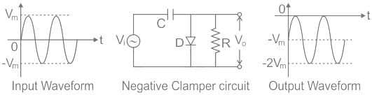
For the given input waveform to the given circuit, what is the minimum value of the output waveform?

Detailed Solution: Question 3

The circuit above is a parallel clipper. When the input is less than 4V, then diode is forward biased and thus output voltage is 4V. When input increases above 4V, the diode is reverse biased and output is equal to the input. Hence, minimum output is 4V.

Test: Clipper & Clamper: Diode Circuits - Question 4

For the given circuit, what is the minimum peak value of the output waveform if the input waveform is 10V square wave with switching time of 1 second?
Assume that the input switches between +10V and -10V DC levels.

Detailed Solution: Question 4

For the positive half of the input, the diode is in the on state and hence acts as a short circuit and hence vo = 0 V. For the negative half cycle, the resistor receives voltage input both from the source and the capacitor which is charged during the positive half of the input. Hence, vo = -20 V.

Test: Clipper & Clamper: Diode Circuits - Question 5

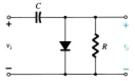
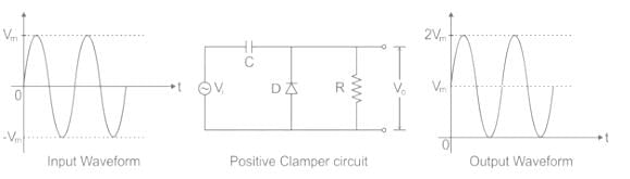
What is the circuit in the given diagram called?

Detailed Solution: Question 5

During the positive half cycle, the diode is forward biased and no signal appears across the output. The capacitor holds the charge in that state. During negative cycle, diode is reverse biased and diode does not conduct. The charge in capacitor is released and is obtained at the output.

Test: Clipper & Clamper: Diode Circuits - Question 6

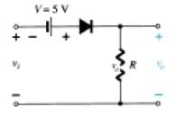
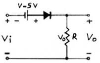
For the given circuit for a 20 Vpeak sinusoidal input vi, what is the value of vi at which the clipping begins?

Detailed Solution: Question 6

Considering the connection of diode, it is evident that the diode becomes reverse biased when vi < -5 V. Hence, clipping starts at -5 V.

Test: Clipper & Clamper: Diode Circuits - Question 7

For the given input waveform to the given circuit, what is the peak value of the output waveform?

Detailed Solution: Question 7

In the given circuit, the diode is in the off stage when vi > 4 V. Hence, when vi > 4 V, vo = vi and hence the peak value of vo = the peak value of vi = 16 V.

Test: Clipper & Clamper: Diode Circuits - Question 8

Which of the following is not a necessary component in a clamper circuit?

Detailed Solution: Question 8

Diode, Capacitor and Resistor are necessary to build a clamper circuit. An independent DC supply is required to bring an additional shift.

Test: Clipper & Clamper: Diode Circuits - Question 9

For the given circuit and input waveform, the peak value of the output is +30V.

Detailed Solution: Question 9

The given circuit is a clamper with an independent DC supply of +10 V. Keeping in mind the connection of the diode and the DC supply, we see that the output waveform is clamped at +10V i.e. it shifts up by +10V. Hence, the maximum value of vo = +30 V.

Test: Clipper & Clamper: Diode Circuits - Question 10

The positive clamper circuit is:

Detailed Solution: Question 10

Analysis:

Whenever there is a capacitor and diode in the circuit of wave-shaping, then it's a clamper circuit.

There are two types of clampers.

(a) Positive clamper

(b) Negative clamper

Positive Clamper: This circuit shifts waveform in the upward direction, which means it adds some positive voltage to the waveform.

Negative Clamper: This circuit shifts waveform in the downward direction, which means it adds some negative voltage to the waveform.

Differentiator: The feedback path in an op-amp differentiator consists of a resistor as shown:

135 videos|183 docs|71 tests
Information about Test: Clipper & Clamper: Diode Circuits Page
In this test you can find the Exam questions for Test: Clipper & Clamper: Diode Circuits solved & explained in the simplest way possible. Besides giving Questions and answers for Test: Clipper & Clamper: Diode Circuits, EduRev gives you an ample number of Online tests for practice
135 videos|183 docs|71 tests
Download as PDF