Civil Engineering (CE) Exam  >  Civil Engineering (CE) Tests  >  Test: Shear Force and Bending Moment - Civil Engineering (CE) MCQ

Test: Shear Force and Bending Moment - Civil Engineering (CE) MCQ


Test Description

10 Questions MCQ Test - Test: Shear Force and Bending Moment

Test: Shear Force and Bending Moment for Civil Engineering (CE) 2024 is part of Civil Engineering (CE) preparation. The Test: Shear Force and Bending Moment questions and answers have been prepared according to the Civil Engineering (CE) exam syllabus.The Test: Shear Force and Bending Moment MCQs are made for Civil Engineering (CE) 2024 Exam. Find important definitions, questions, notes, meanings, examples, exercises, MCQs and online tests for Test: Shear Force and Bending Moment below.
Solutions of Test: Shear Force and Bending Moment questions in English are available as part of our course for Civil Engineering (CE) & Test: Shear Force and Bending Moment solutions in Hindi for Civil Engineering (CE) course. Download more important topics, notes, lectures and mock test series for Civil Engineering (CE) Exam by signing up for free. Attempt Test: Shear Force and Bending Moment | 10 questions in 30 minutes | Mock test for Civil Engineering (CE) preparation | Free important questions MCQ to study for Civil Engineering (CE) Exam | Download free PDF with solutions
Test: Shear Force and Bending Moment - Question 1

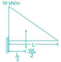
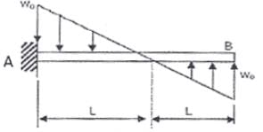
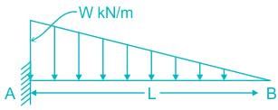
The maximum bending moment at 'A' for beam shown in the given figure is given by:
Detailed Solution for Test: Shear Force and Bending Moment - Question 1

BM = P × x where P = force applied and x = distance of force application from point where BM is to be calculated

Calculation:
Load acted from centroid of the load triangle.
Load = WL/2 acted at L/3 distance from fixed end
 (as per sign convention -ve sign is used)

Test: Shear Force and Bending Moment - Question 2

What is the bending moment at end supports of a simply supported beam?

Detailed Solution for Test: Shear Force and Bending Moment - Question 2

At the end supports, the moment (couple) developed is zero, because there is no distance to take the perpendicular acting load. As the distance is zero, the moment is obviously zero.

1 Crore+ students have signed up on EduRev. Have you? Download the App
Test: Shear Force and Bending Moment - Question 3

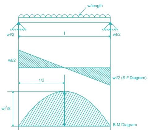
The shapes of the bending moment diagram for a uniform cantilever beam carrying a uniformly distributed load over its length is

Detailed Solution for Test: Shear Force and Bending Moment - Question 3


is the equation of parabola.

Test: Shear Force and Bending Moment - Question 4

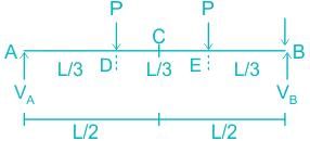
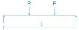
A simply supported beam of span L is subjected to two point loads, each of magnitude P, acting at one third of the span, as shown in the figure below. Which of the follloing statements is correct about the nature of the BMD?
Detailed Solution for Test: Shear Force and Bending Moment - Question 4


The point loads are applied symmetrically to the simply supported beam with respect to mid-span (or point C), so the vertical reaction at both supports is equal and is half the applied load.
VA = VB = P
Calculating the bending moment at point D

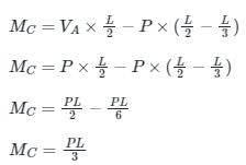
Calculating the bending moment at point C

The bending moment at points A and B is zero because supports A and B are simply supports (roller and hinge).

Hence the bending moment is constant in the middle one-third part of the beam.

Test: Shear Force and Bending Moment - Question 5

What is the maximum shear force, when a cantilever beam is loaded with udl throughout?

Detailed Solution for Test: Shear Force and Bending Moment - Question 5

In cantilever beams, the maximum shear force occurs at the fixed end. In the free end, there is zero shear force. As we need to convert the udl in to load, we multiply the length of the cantilever beam with udl acting upon. For maximum shear force to obtain we ought to multiply load and distance and it surely occurs at the fixed end (w×l).

Test: Shear Force and Bending Moment - Question 6

A concentrated load P acts on a simply supported beam of span L at a distance L/3 from the left support. The bending moment at the point of application of the load is given by

Detailed Solution for Test: Shear Force and Bending Moment - Question 6

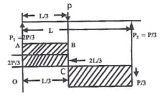
For vertical equilibrium
R1 + R2 = P
Taking moment about R1, we have


The bending moment at the point of application of load = Area under OABC

Test: Shear Force and Bending Moment - Question 7

What does the slope of a bending moment curve as a function of distance represent?

Detailed Solution for Test: Shear Force and Bending Moment - Question 7

Bending moment Diagram:
Bending moment diagrams are simply plots of the bending moment (on the y-axis) versus the position of various points along the beam (on the x-axis).
For UDL(Uniformly Distributed Load)

Relationship between Shear force, Bending moment and Loading rate

  • −(ds/dx) = w i.e. negative slope of Shear force diagram at any section will be equal to the load intensity at that section
  • (dM/dx) = S i.e. The slope of Bending moment diagram at any section of a loaded beam will be equal to Intensity of shear force at that section

Additional Information
For point load

  • Shear force is constant. So SFD is rectangular. Hence slope of SFD at any section will be 0.
  • Bending Moment is of one degree. So BMD is Triangular and Slope of BMD at any section will be constant and equal to Shear force.

For UDL

  • Shear force is of one degree. So SFD is Triangular and its slope at any section will be constant and equal to load intensity.
  • Bending moment is of two degree. So BMD is parabolic and its slope at any section will be equal to shear force intensity at that section.
Test: Shear Force and Bending Moment - Question 8

Sagging, the bending moment occurs at the _____ of the beam.

Detailed Solution for Test: Shear Force and Bending Moment - Question 8

The positive bending moment is considered when it causes convexity downward or concavity at top. This is sagging. In simply supported beams, it occurs at mid span because the bending moment at the supports obviously will be zero hence the positive bending moment occurs in the mid span.

Test: Shear Force and Bending Moment - Question 9

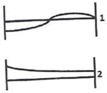
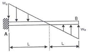
A cantilever beam carriers the anti symmetric load as shown, where w is the peak intensity of the distributed load. Qualitatively, the correct bending moment diagram for the beam is
Detailed Solution for Test: Shear Force and Bending Moment - Question 9

Here make hit and trial method
Consider first option (A) of moment diagram.

V = dM/dx
At right end B, slope must be zero as there is no shear force at B so option A is wrong.
Now, consider option (B)
Due to symmetric load intensity at left side too the shear force equal to zero so slope at left side must be zero. So option (B) wrong.


Now consider option (C)
Here at both ends, slope is zero means shear force is zero and also when we move from right to left, the rate of increase of shear force decreases due triangular shape of load intensity and at middle slope should be maximum and there after decreases so in option (C) all these criterion fulfills. Here (C) is the correct option.


As far as (D) option is concerned its middle part slope and right most part slope is strictly not agreeing with the load shown.

Test: Shear Force and Bending Moment - Question 10

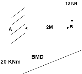
What will be the variation in BMD for the diagram? [Assume l = 2m].
The variation in BMD for the diagram [Assume l = 2m] is Triangular

Detailed Solution for Test: Shear Force and Bending Moment - Question 10

At support B, the BM is zero. The beam undergoes maximum BM at fixed end.
By joining the base line, free end and maximum BM point. We obtain a right angled triangle.
The base line free end & maximum BM point

Information about Test: Shear Force and Bending Moment Page
In this test you can find the Exam questions for Test: Shear Force and Bending Moment solved & explained in the simplest way possible. Besides giving Questions and answers for Test: Shear Force and Bending Moment, EduRev gives you an ample number of Online tests for practice

Top Courses for Civil Engineering (CE)

Download as PDF

Top Courses for Civil Engineering (CE)