Electrical Engineering (EE) Exam  >  Electrical Engineering (EE) Tests  >  Test: ESE Electrical - 2 - Electrical Engineering (EE) MCQ

Test: ESE Electrical - 2 - Electrical Engineering (EE) MCQ


Test Description

30 Questions MCQ Test - Test: ESE Electrical - 2

Test: ESE Electrical - 2 for Electrical Engineering (EE) 2024 is part of Electrical Engineering (EE) preparation. The Test: ESE Electrical - 2 questions and answers have been prepared according to the Electrical Engineering (EE) exam syllabus.The Test: ESE Electrical - 2 MCQs are made for Electrical Engineering (EE) 2024 Exam. Find important definitions, questions, notes, meanings, examples, exercises, MCQs and online tests for Test: ESE Electrical - 2 below.
Solutions of Test: ESE Electrical - 2 questions in English are available as part of our course for Electrical Engineering (EE) & Test: ESE Electrical - 2 solutions in Hindi for Electrical Engineering (EE) course. Download more important topics, notes, lectures and mock test series for Electrical Engineering (EE) Exam by signing up for free. Attempt Test: ESE Electrical - 2 | 150 questions in 180 minutes | Mock test for Electrical Engineering (EE) preparation | Free important questions MCQ to study for Electrical Engineering (EE) Exam | Download free PDF with solutions
Test: ESE Electrical - 2 - Question 1

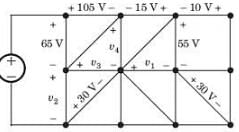
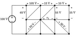
Consider the circuit graph shown in fig. Each branch of circuit graph represent a circuit element. The value of voltage v1 is:
Detailed Solution for Test: ESE Electrical - 2 - Question 1

100 = 65 + v2
⇒ v= 35 V

v3 - 30 = v2 
⇒ v3 = 65 V

105 + v4 - v- 65 = 0
⇒ v4 = 25 V

v4 + 15 - 55 + v1 = 0
⇒ v1 = 15 V 

Test: ESE Electrical - 2 - Question 2

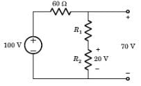
Find the value of R1.

Detailed Solution for Test: ESE Electrical - 2 - Question 2

Voltage across 60 Ω resistor = 30 V 
Current = 30 / 60 = 0.5 A 
Voltage across R1 is = (70 - 20) V = 50 V
R1 = 50 / 0.5 = 100 Ω

1 Crore+ students have signed up on EduRev. Have you? Download the App
Test: ESE Electrical - 2 - Question 3

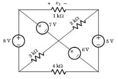
Find the value of v1.

Detailed Solution for Test: ESE Electrical - 2 - Question 3

If we go from +ve side of 1 kΩ through 7 V, 6 V and 5 V
We get, v1 = 7 + 6 - 5 = 8 V

Test: ESE Electrical - 2 - Question 4

Consider a current source i(t) connected across a 0.5 mH inductor, where i(t) = 0 A for t < 0 and i(t) = (8e-250t - 4e-1000t) A for t ≥ 0. The voltage across the inductor at t = 0 s is

Detailed Solution for Test: ESE Electrical - 2 - Question 4

When current source i(t) connected across an inductor(L), then the voltage across the inductor is given as

When voltage source v(t) connected across a capacitor(C), then the current across the capacitor is given as

Calculation:

Given i(t) = (8e-250t - 4e-1000t) A for t ≥ 0, L = 0.5 mH

Then the voltage across the inductor is given as

At t = 0 its value is given as

VL = 0.5 × 10-3 × (- 2000 + 4000)

VL = 1 V

Test: ESE Electrical - 2 - Question 5

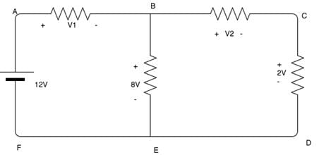
Calculate the value of V1 and V2.

Detailed Solution for Test: ESE Electrical - 2 - Question 5

Using KVL,
12 - V1 - 8 = 0.
V1 =  4V.
8 - V2 - 2=0.
V2 = 6V.

Test: ESE Electrical - 2 - Question 6

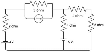
What is the voltage across the 5 ohm resistor if current source has current of 17/3 A?
Detailed Solution for Test: ESE Electrical - 2 - Question 6

Assuming i1 and i2 be the currents in loop 1 and 2 respectively. In loop 1, 4 + 2i1+3(i1 - 17/3) + 4(i1 - i2) + 5 = 0
In loop 2, i2(4 + 1 + 5)-4i1 - 5 = 0
⇒ -4i1 + 10i2 = 5.
Solving these equations simultaneously i2 = 1.041A and i1 = 1.352A
V= i2 x 5 = 5.21V.

Test: ESE Electrical - 2 - Question 7

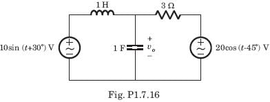
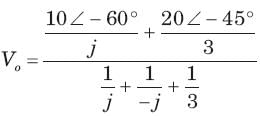
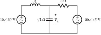
v(t) = ?

Detailed Solution for Test: ESE Electrical - 2 - Question 7

10 sin (t + 30°) = 10 cos (t - 60°)


Test: ESE Electrical - 2 - Question 8

[H] = ?

​ ​ ​

Detailed Solution for Test: ESE Electrical - 2 - Question 8


 ..........(i)

Test: ESE Electrical - 2 - Question 9

 In a delta-connected load, the relation between line voltage and the phase voltage is?

Detailed Solution for Test: ESE Electrical - 2 - Question 9

In a delta-connected load, the relation between line voltage and the phase voltage is line voltage = phase voltage.

Test: ESE Electrical - 2 - Question 10

The three impedances Z1 = 20∠30⁰Ω, Z2 = 40∠60⁰Ω, Z3 = 10∠-90⁰Ω are delta-connected to a 400V, 3 – Ø system. Find the phase current IY.

Detailed Solution for Test: ESE Electrical - 2 - Question 10

The voltage VYB is VYB = 400 ∠ -120⁰V. The impedance Z2 is Z2 = 40 ∠ 60⁰Ω

⇒ IY = (400 ∠ -120o)/(40 ∠ 60o)=(-10 + j0)A.

Test: ESE Electrical - 2 - Question 11

If the radius of a sphere is 1/(4π)m and the electric flux density is 16π units, the total flux is given by,

Detailed Solution for Test: ESE Electrical - 2 - Question 11

Total flux leaving the entire surface is, ψ = 4πr2D from Gauss law. Ψ = 4π(1/16π2) X 16π = 4.

Test: ESE Electrical - 2 - Question 12

Coulomb is the unit of which quantity?

Detailed Solution for Test: ESE Electrical - 2 - Question 12

The standard unit of charge is Coulomb. One coulomb is defined as the 1 Newton of force applied on 1 unit of electric field

Test: ESE Electrical - 2 - Question 13

The auto-correlation function Rx(τ) satisfies which one of the following properties?

Detailed Solution for Test: ESE Electrical - 2 - Question 13

The autocorrelation function of a signal is defined as the measure of similarity or coherence between a signal and its time delayed version. Thus, autocorrelation is the correlation of a signal with itself.

Property of autocorrelation function:

  • The autocorrelation function of energy signals exhibits complex conjugate symmetry, which means the real part of autocorrelation function R(τ) is an even function of delay parameter ( τ) and the imaginary part of R(τ) is an odd function of the parameter τ. Thus,

R(τ)=R∗(−τ)

Test: ESE Electrical - 2 - Question 14

X(z) of a system is specified by a pole zero pattern in fig.

Detailed Solution for Test: ESE Electrical - 2 - Question 14

All gives the same z transform with different ROC. So all are the solution.

Test: ESE Electrical - 2 - Question 15

Consider three different signal

fig.shows the three different region. Choose the correct option for the ROC of signal

R1  , R2 , R3

Detailed Solution for Test: ESE Electrical - 2 - Question 15

x1[n] is right-sided signal

Test: ESE Electrical - 2 - Question 16

Given the transform pair below. Determine the time signal y(t) and choose correct option.

Q.   

Detailed Solution for Test: ESE Electrical - 2 - Question 16

Test: ESE Electrical - 2 - Question 17

Given the transform pair

Determine the Laplace transform Y(s) of the given time signal in question and choose correct option.

Que: y(t) = x(t - 2)

Detailed Solution for Test: ESE Electrical - 2 - Question 17

Test: ESE Electrical - 2 - Question 18

Consider a periodic signal x[n] with period N and FS coefficients X [k]. Determine the FS coefficients Y [k] of the signal y[n] given in question.

Que: y[n] = x[n] - x[n + N/2 ] , (assume that N is even)

Detailed Solution for Test: ESE Electrical - 2 - Question 18

Test: ESE Electrical - 2 - Question 19

Consider a periodic signal x[n] with period N and FS coefficients X [k]. Determine the FS coefficients Y [k] of the signal y[n] given in question.

y[n] = (-1)nx[n], (assume that N is even)

Detailed Solution for Test: ESE Electrical - 2 - Question 19

With N even

Test: ESE Electrical - 2 - Question 20

Determine the Fourier series coefficient for given periodic signal x(t).

Que: x(t) as shown in fig.

​ ​ ​

Detailed Solution for Test: ESE Electrical - 2 - Question 20

Test: ESE Electrical - 2 - Question 21

A single tone 4 kHz message signal is sampled with 9 kHz, 7 kHz and 5 kHz.  Aliasing effect will be seen in the reconstructed signal, when the signal is sampled with

Detailed Solution for Test: ESE Electrical - 2 - Question 21

Concept:
The sampling theorem states that “a signal can be exactly reproduced if it is sampled at the rate fs which is greater than twice the maximum frequency W in the modulating signal."
If the sampled frequency is less than the Nyquist frequency, overlapping of lower and upper sidebands known as aliasing takes place.
The main reason for aliasing is under-sampling, i.e. sampling the signal at a frequency less than twice the Nyquist rate.
fs < 2fm
fs = Sampling frequency
f= Modulating frequency
Application:
The minimum sampling rate to avoid aliasing will be:
fs = 2 × 2fm = 2 × 4 kHz
fs = 8 kHz
∴ For fs ≥ 8 kHz, the sampling frequency will satisfy the Nyquist rate and no aliasing will take place.
And for both 7 kHz and 5 kHz sampling rates, the Aliasing effect will be seen in the reconstructed signal as the sampling frequency is less than the Nyquist Rate.

Aliasing is explained with the help of the spectrum as shown:

Test: ESE Electrical - 2 - Question 22

If X(k) is the DFT of x(n) which is defined as x(n)=x1(n)+jx2(n), 0≤ n≤ N-1, then what is the DFT of x1(n)?

Detailed Solution for Test: ESE Electrical - 2 - Question 22

Test: ESE Electrical - 2 - Question 23

What is the number of filter coefficients that specify the frequency response for h(n) symmetric?

Detailed Solution for Test: ESE Electrical - 2 - Question 23

Explanation: We know that, for a symmetric h(n), the number of filter coefficients that specify the frequency response is (M+1)/2 when M is odd and M/2 when M is even.

Test: ESE Electrical - 2 - Question 24

 What is the number of filter coefficients that specify the frequency response for h(n) anti-symmetric?

Detailed Solution for Test: ESE Electrical - 2 - Question 24

We know that, for a anti-symmetric h(n) h(M-1/2)=0 and thus the number of filter coefficients that specify the frequency response is (M-1)/2 when M is odd and M/2 when M is even.

Test: ESE Electrical - 2 - Question 25

The Laplace transform of a transportation Iag of 10 seconds is:

Detailed Solution for Test: ESE Electrical - 2 - Question 25

Test: ESE Electrical - 2 - Question 26

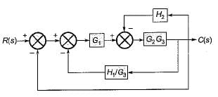
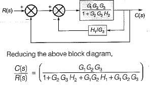
The ratio C(s)/R(s) for the system shown in figure below is
 

Detailed Solution for Test: ESE Electrical - 2 - Question 26

On shifting the take-off point beyond the block G3 and combining blocks G2 and G3, the given block diagram is reduced as shown below.

The block diagram is further reduced as shown below.

Test: ESE Electrical - 2 - Question 27

The solution of the differential equation

Detailed Solution for Test: ESE Electrical - 2 - Question 27

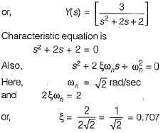
Taking Laplace transform on both sides of the given differential equation, we get (s2 + 2s + 2) Y(s) = 3

Since, ξ < 1, therefore given system is underdamped.

Test: ESE Electrical - 2 - Question 28

Assertion (A): A system is said to be stable if the impulse response approaches zero for sufficiently large time.
Reason (R): If the impulse response approaches infinity for sufficiently large time, the system is said to be unstable

Detailed Solution for Test: ESE Electrical - 2 - Question 28

Both assertion and reason are individually true. The correct reason for assertion is BIBO stability criteria,

Test: ESE Electrical - 2 - Question 29

The open-loop transfer function of a unity feedback control system is given by:

The centroid and the angle of root locus asymptotes are respectively

Detailed Solution for Test: ESE Electrical - 2 - Question 29


Number of open loop poies = P = 3
and number of open loop zeros = Z = 1
Poles are at: s = -1 ± j, 0 and zero is at s = -2


= 0
Here, P - Z = 2
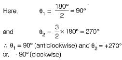
So, angle of asymptotes are given by

Test: ESE Electrical - 2 - Question 30

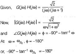
The gain margin of a control system having the loop transfer function G(s)H(s) = 

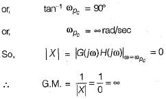
Detailed Solution for Test: ESE Electrical - 2 - Question 30


View more questions
Information about Test: ESE Electrical - 2 Page
In this test you can find the Exam questions for Test: ESE Electrical - 2 solved & explained in the simplest way possible. Besides giving Questions and answers for Test: ESE Electrical - 2, EduRev gives you an ample number of Online tests for practice

Top Courses for Electrical Engineering (EE)

Download as PDF

Top Courses for Electrical Engineering (EE)