Electrical Engineering (EE) Exam  >  Electrical Engineering (EE) Tests  >  Test: ESE Electrical - 3 - Electrical Engineering (EE) MCQ

Test: ESE Electrical - 3 - Electrical Engineering (EE) MCQ


Test Description

30 Questions MCQ Test - Test: ESE Electrical - 3

Test: ESE Electrical - 3 for Electrical Engineering (EE) 2024 is part of Electrical Engineering (EE) preparation. The Test: ESE Electrical - 3 questions and answers have been prepared according to the Electrical Engineering (EE) exam syllabus.The Test: ESE Electrical - 3 MCQs are made for Electrical Engineering (EE) 2024 Exam. Find important definitions, questions, notes, meanings, examples, exercises, MCQs and online tests for Test: ESE Electrical - 3 below.
Solutions of Test: ESE Electrical - 3 questions in English are available as part of our course for Electrical Engineering (EE) & Test: ESE Electrical - 3 solutions in Hindi for Electrical Engineering (EE) course. Download more important topics, notes, lectures and mock test series for Electrical Engineering (EE) Exam by signing up for free. Attempt Test: ESE Electrical - 3 | 150 questions in 180 minutes | Mock test for Electrical Engineering (EE) preparation | Free important questions MCQ to study for Electrical Engineering (EE) Exam | Download free PDF with solutions
Test: ESE Electrical - 3 - Question 1

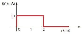
The current in a 100 μF capacitor is shown in fig. If capacitor is initially uncharged, then the waveform for the voltage across it is:
Detailed Solution for Test: ESE Electrical - 3 - Question 1


This 0.2 V increases linearly from 0 to 0.2 V. Then current is zero. So capacitor hold this voltage.

Test: ESE Electrical - 3 - Question 2

The voltage across a 100 μF capacitor is shown in fig. The waveform for the current in the capacitor is:

Detailed Solution for Test: ESE Electrical - 3 - Question 2


= 600 mA
For 1 ms < t < 2 ms, 

1 Crore+ students have signed up on EduRev. Have you? Download the App
Test: ESE Electrical - 3 - Question 3

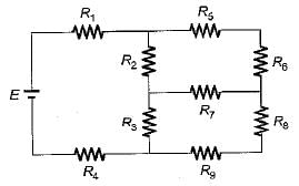
 Which of the following is ​​​​true about the circuit shown below?

Detailed Solution for Test: ESE Electrical - 3 - Question 3

Number of junction points for the above circuit is 6

Test: ESE Electrical - 3 - Question 4

In the circuit of fig. v = 0 for t > 0. The initial condition are v(0) = 6V and dv(0) /dt =-3000 V s. The v(t) for t > 0 is

Detailed Solution for Test: ESE Electrical - 3 - Question 4


⇒ 

⇒ 


Test: ESE Electrical - 3 - Question 5

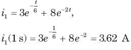
Circuit is shown in fig. Initial conditions are i1(0) = i2(0) =11A
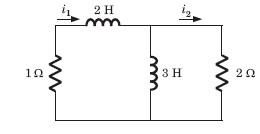
i1 (1s) = ?

Detailed Solution for Test: ESE Electrical - 3 - Question 5


In differential equation putting t = 0 and sovling

Test: ESE Electrical - 3 - Question 6

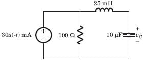
v(t ) =? for t > 0

Detailed Solution for Test: ESE Electrical - 3 - Question 6


Test: ESE Electrical - 3 - Question 7

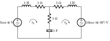
The circuit is as shown in fig.

i1( t) = ?

Detailed Solution for Test: ESE Electrical - 3 - Question 7


Test: ESE Electrical - 3 - Question 8

[Y] = ?

 ​ ​ ​

Detailed Solution for Test: ESE Electrical - 3 - Question 8

I1 = (V1 - V2) Yab + V1Yab 
⇒ I1 = V1(Ya + Yab) - V2Yab .....(i)
I2 = (V2 - V1)Yab + V2Yb = -V1Yab + V2(Yb + Yab) .....(ii)

Test: ESE Electrical - 3 - Question 9

If the load impedance is Z∠Ø, the expression obtained for current (IY) is?

Detailed Solution for Test: ESE Electrical - 3 - Question 9

As the load impedance is Z∠Ø, the current flows in the three load impedances and the current flowing in the Y impedance is IY = VYB∠120⁰/Z∠Ø = (V/Z)∠-120-Ø.

Test: ESE Electrical - 3 - Question 10

The three impedances Z1 = 20∠30⁰Ω, Z2 = 40∠60⁰Ω, Z3 = 10∠-90⁰Ω are delta-connected to a 400V, 3 – Ø system. Find the line current I1.

Detailed Solution for Test: ESE Electrical - 3 - Question 10

The line current I1 is the difference of IR and IB. So the line current I1 is I1 = IR – IB = (51.96 + j10) A.

Test: ESE Electrical - 3 - Question 11

Find the force between 2C and -1C separated by a distance 1m in air(in newton). 

Detailed Solution for Test: ESE Electrical - 3 - Question 11

F = q1q2/(4∏εor2) = -2 X 9/(10-9 X 12) = -18 X 109.

Test: ESE Electrical - 3 - Question 12

Two charges 1C and -4C exists in air. What is the direction of force?

Detailed Solution for Test: ESE Electrical - 3 - Question 12

Since the charges are unlike, the force will be attractive. Thus the force directs from 1C to -4C.

Test: ESE Electrical - 3 - Question 13

The sampling of a function f(t) = sin(2πf0t) starts from zero-crossing. The signal can be detected, if sampling time T is:

Detailed Solution for Test: ESE Electrical - 3 - Question 13

Because fs ≤ 2f0,

Ts ≤ .

Test: ESE Electrical - 3 - Question 14

X(z) has poles at z =1/2 and z =-1.If x [1] = 1 x [-1] = 1, and the ROC includes the point z = 34. The time signal x[n] is

Detailed Solution for Test: ESE Electrical - 3 - Question 14

Since the ROC includes the z = 3/4, ROC is

Test: ESE Electrical - 3 - Question 15

The z-transform of a signal x[n] is given by

If X (z) converges on the unit circle, x[n] is

Detailed Solution for Test: ESE Electrical - 3 - Question 15

Since X(z) converges on |z| = 1. So ROC must include this circle.

Test: ESE Electrical - 3 - Question 16

Given the transform pair

Determine the Laplace transform Y(s) of the given time signal in question and choose correct option.

Q.  

Detailed Solution for Test: ESE Electrical - 3 - Question 16

Test: ESE Electrical - 3 - Question 17

Given the transform pair

Determine the Laplace transform Y(s) of the given time signal in question and choose correct option.

Q. y(t) = e-t x(t)

Detailed Solution for Test: ESE Electrical - 3 - Question 17

Test: ESE Electrical - 3 - Question 18

Consider a discrete-time periodic signal

with period  N = 10, Also y[n] = x[n] - x[n-1]

Q. The fundamental period of y[n] is

Detailed Solution for Test: ESE Electrical - 3 - Question 18

y[n] is shown is fig.

It has fundamental period of 10.

Test: ESE Electrical - 3 - Question 19

Consider a continuous time periodic signal x(t) given by

Detailed Solution for Test: ESE Electrical - 3 - Question 19

Test: ESE Electrical - 3 - Question 20

Determine the Fourier series coefficient for given periodic signal x(t).

x(t) = sin2t

Detailed Solution for Test: ESE Electrical - 3 - Question 20

Test: ESE Electrical - 3 - Question 21

The figure given below shows the Fourier spectra of signal x(t) and y(t).

The Nyquist sampling rate for x(t) y(t) is_________.

Detailed Solution for Test: ESE Electrical - 3 - Question 21

Concept:
Multiplication in the time domain is the convolution in the frequency domain and the maximum frequency of convolution of the signal is the sum of individual frequencies, i.e.
If z(t) = x(t) y(t)
The maximum frequency of Z(ω) = ωx + ωy
where ωx is the maximum frequency of signal x(t)
ωy is the maximum frequency of signal y(t)
Application:
The maximum frequency present in x(t) is:

Similarly, the maximum frequency present in y(t) is:

Now, the maximum frequency present in z(t) = x(t) y(t) will be:
fz = fx + fy
fz = 250 kHz
Nyquist sampling frequency will now be:
fN = 2 × fz
fN = 500 kHz

Test: ESE Electrical - 3 - Question 22

If g(n) is a real valued sequence of 2N points and x1(n)=g(2n) and x2(n)=g(2n+1), then what is the value of G(k), k=0,1,2…N-1? 

Detailed Solution for Test: ESE Electrical - 3 - Question 22

Given g(n) is a real valued 2N point sequence. The 2N point sequence is divided into two N point sequences x1(n) and x2(n)
Let x(n)= x1(n)+jx2(n)
=> X1(k)= 1/2 [X*(k)+X*(N-k)] and X2(k)= 1/2j [X*(k)-X*(N-k)] We know that g(n)= x1(n)+x2(n)
=>G(k)= X1(k)+W2kNX2(k), k=0,1,2…N-1.

Test: ESE Electrical - 3 - Question 23

The anti-symmetric condition with M even is not used in the design of which of the following linear-phase FIR filter?

Detailed Solution for Test: ESE Electrical - 3 - Question 23

When h(n)=-h(M-1-n) and M is even, we know that H(0)=0. Thus it is not used in the design of a low pass linear phase FIR filter.

Test: ESE Electrical - 3 - Question 24

The anti-symmetric condition is not used in the design of low pass linear phase FIR filter.

Detailed Solution for Test: ESE Electrical - 3 - Question 24

We know that if h(n)=-h(M-1-n) and M is odd, we get H(0)=0 and H(π)=0. Consequently, this is not suitable as either a low pass filter or a high pass filter and when h(n)=-h(M-1-n) and M is even, we know that H(0)=0. Thus it is not used in the design of a low pass linear phase FIR filter. Thus the anti-symmetric condition is not used in the design of low pass linear phase FIR filter.

Test: ESE Electrical - 3 - Question 25

The phenomena of ‘limit cycles’ and ‘jump resonance’ are observed in

Detailed Solution for Test: ESE Electrical - 3 - Question 25

The phenomena of 'limit cycles' and 'jump resonance' are observed in non-linear systems.

Limit cycles refer to a recurring pattern of behavior in a dynamic system, where the system's state variables repeat themselves over time. In non-linear systems, limit cycles can arise due to the interactions between various system components and their non-linear characteristics.

Jump resonance, also known as bifurcation or sudden change in behavior, occurs in non-linear systems when a small change in a parameter or input leads to a significant and abrupt change in the system's response.

Linear systems, option (A), typically do not exhibit limit cycles or jump resonance since they follow predictable and proportional relationships between inputs and outputs. Distributed systems, option (B), refer to systems that are spread across multiple interconnected components, but the presence of limit cycles or jump resonance is not specific to distributed systems.

Discrete time systems, option (D), involve systems where the variables are updated at discrete time intervals. While discrete time systems can exhibit complex behavior, the presence of limit cycles and jump resonance is more commonly associated with continuous-time non-linear systems.

Therefore, the correct answer is option (C) non-linear systems. Limit cycles and jump resonance are observed in non-linear systems due to their inherent complexity and interactions between system components.

Test: ESE Electrical - 3 - Question 26

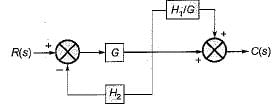
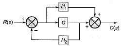
The transfer function C(s)/R(s) for the system described by the block diagram shown below is given by:
Detailed Solution for Test: ESE Electrical - 3 - Question 26

On shifting the take-off point beyond block G, we have the reduced block diagram as shown below:

On further reducing the above block diagram, we get the block diagram as shown below.

Test: ESE Electrical - 3 - Question 27

In time domain specification, the time delay is the time required for the response to reach

Detailed Solution for Test: ESE Electrical - 3 - Question 27

Delay time (td) is the time required for the response curve to reach 50% of the final value.

Test: ESE Electrical - 3 - Question 28

The open loop transfer function of a unity feedback system is
What is the range of value of K so that the closed loop system is absolutely stable?

Detailed Solution for Test: ESE Electrical - 3 - Question 28

The characteristic equation is,
1 + G(s)H(s) = 0 

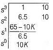
The Routh's array is:

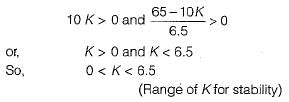
For absolute stability, we have:

Test: ESE Electrical - 3 - Question 29

Assertion (A) : An addition of real pole at s = - p0 in the transfer function G(s)H(s) of a control system results in the increase of stability margin.
Reason (R) : An addition of real pole at s = - p0 in the transfer function G(s)H(s) will make the resultant root loci bend towards the right.

Detailed Solution for Test: ESE Electrical - 3 - Question 29

Addition of real pole to an open loop T.F. decreases the stability because root locus shifts towards right of s-plane. Hence, assertion is a false statement.

Test: ESE Electrical - 3 - Question 30

Gain crossover frequency is the frequency at which the gain of G(jω) is

Detailed Solution for Test: ESE Electrical - 3 - Question 30

At gain crossover frequency 
∴ Gain in dB = 20 log |G(jω|
= 20 log 1 = 0 dB

View more questions
Information about Test: ESE Electrical - 3 Page
In this test you can find the Exam questions for Test: ESE Electrical - 3 solved & explained in the simplest way possible. Besides giving Questions and answers for Test: ESE Electrical - 3, EduRev gives you an ample number of Online tests for practice
Top Courses for Electrical Engineering (EE)

Download as PDF

Top Courses for Electrical Engineering (EE)