Test: Sequential Logic Circuit in Digital Circuit - Electronics and Communication Engineering (ECE) MCQ
10 Questions MCQ Test - Test: Sequential Logic Circuit in Digital Circuit

Read the following paragraph and answer the questions.
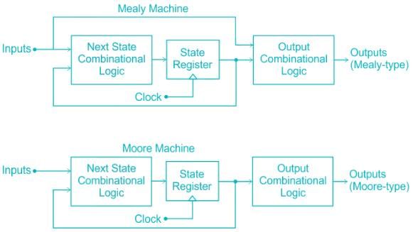
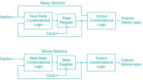
A digital counter is a set of flipflops whose states change in response to the pulses applied at Input. Counters can be asynchronous counters or synchronous counters. A counter is an example of a state machine; the number of states is called the modulus. Two basic types of state machines are the Moore and the Mealy. In Moore machine, the combinational logic is a gate array with outputs that determine the next state of the flip-flops in the memory. For Mealy machine, the present state affects just as in Moore machine but in addition, the inputs also affect the outputs.
Q. Which of the following statements is not correct about Glitch?
A digital counter is a set of flipflops whose states change in response to the pulses applied at Input. Counters can be asynchronous counters or synchronous counters. A counter is an example of a state machine; the number of states is called the modulus. Two basic types of state machines are the Moore and the Mealy. In Moore machine, the combinational logic is a gate array with outputs that determine the next state of the flip-flops in the memory. For Mealy machine, the present state affects just as in Moore machine but in addition, the inputs also affect the outputs.
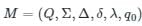 is a 6-tuple notation, where
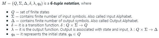

Comprehension:
Read the following paragraph and answer the questions.
A digital counter is a set of flipflops whose states change in response to the pulses applied at Input. Counters can be asynchronous counters or synchronous counters. A counter is an example of a state machine; the number of states is called the modulus. Two basic types of state machines are the Moore and the Mealy. In Moore machine, the combinational logic is a gate array with outputs that determine the next state of the flip-flops in the memory. For Mealy machine, the present state affects just as in Moore machine but in addition, the inputs also affect the outputs.
Q. Which of the following statements is correct about counter?
Read the following paragraph and answer the questions.
A digital counter is a set of flipflops whose states change in response to the pulses applied at Input. Counters can be asynchronous counters or synchronous counters. A counter is an example of a state machine; the number of states is called the modulus. Two basic types of state machines are the Moore and the Mealy. In Moore machine, the combinational logic is a gate array with outputs that determine the next state of the flip-flops in the memory. For Mealy machine, the present state affects just as in Moore machine but in addition, the inputs also affect the outputs.
Comprehension:
Read the following paragraph and answer the questions.
A digital counter is a set of flipflops whose states change in response to the pulses applied at Input. Counters can be asynchronous counters or synchronous counters. A counter is an example of a state machine; the number of states is called the modulus. Two basic types of state machines are the Moore and the Mealy. In Moore machine, the combinational logic is a gate array with outputs that determine the next state of the flip-flops in the memory. For Mealy machine, the present state affects just as in Moore machine but in addition, the inputs also affect the outputs.
In a 4-bit asynchronous binary counter, each D flip-flop is negative edge-triggered and has a propagation delay for 10 nanoseconds. What is the highest frequency allowed for the counter to avoid problems due to propagation delay?
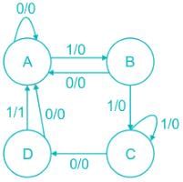
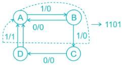
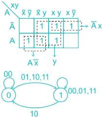
The sequence detected by the state diagram shown below is
Read the following paragraph and answer the questions.
A digital counter is a set of flipflops whose states change in response to the pulses applied at Input. Counters can be asynchronous counters or synchronous counters. A counter is an example of a state machine; the number of states is called the modulus. Two basic types of state machines are the Moore and the Mealy. In Moore machine, the combinational logic is a gate array with outputs that determine the next state of the flip-flops in the memory. For Mealy machine, the present state affects just as in Moore machine but in addition, the inputs also affect the outputs.
Q. A binary ripple counter is required to count upto 16, 38310. If the clock frequency is 8.192 MHz, the number of flip-flops required and frequency of the output of MSB respectively are

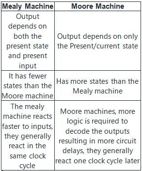
A finite state machine in which
- the output is a function of the current state and Inputs
- the output is a function of only the current state
Q. Which of the following machines is respectively correct for these styles?
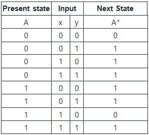
The following state diagram represents which of the input equation. (Given : DA = [A, x, y]) (Where DA denotes a DFF with output A. The x and y are the inputs to the circuit)

The number of directed arcs terminating on any state of a state diagram is
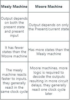
Which of the following is true in case of Moore Machine?


Important Questions for Sequential Logic Circuit in Digital Circuit
Sequential Logic Circuit in Digital Circuit MCQs with Answers
Online Tests for Sequential Logic Circuit in Digital Circuit
|
© EduRev
|
Education Revolution
|


|


