Test: Step Up Choppers - Electrical Engineering (EE) MCQ
10 Questions MCQ Test - Test: Step Up Choppers
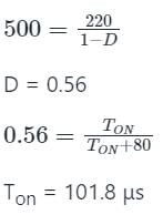
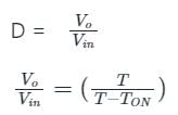
A step-up chopper is used to deliver a load voltage of 500 V from a 220 V d.c. source. If the blocking period of the thyristor is 80 μs, the required pulse width is -
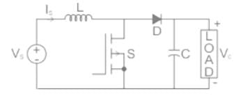
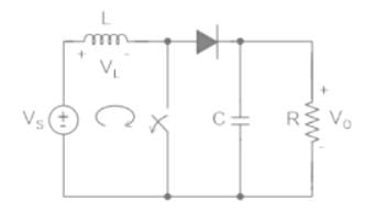
A self-commutating switch SW, operated at duty cycle δ is used to control the load voltage as shown in the figure.
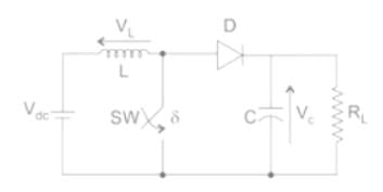
Under steady state operating conditions, the average voltage across the inductor and the capacitor respectively, are

Under steady state operating conditions, the average voltage across the inductor and the capacitor respectively, are
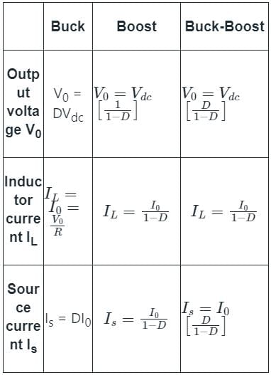
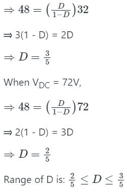
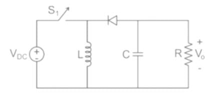
The input voltage VDC of the buck-boost converter shown below varies from 32 V to 72 V. Assume that all components are ideal, inductor current is continuous, and output voltage is ripple free. The range of duty ratio D of the converter for which the magnitude of the steady-state output voltage remains constant at 48 V is

If the duty ratio of a boost converter is 50 percent, the output voltage corresponding to an input of 25 V is
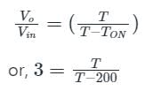
A step-up chopper is fed with 200 V. The conduction time of the thyristor is 200 µs and the required output is 600 V. If the frequency of operation is kept constant and the pulse width is halved, what will be the new output voltage?
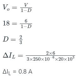
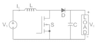
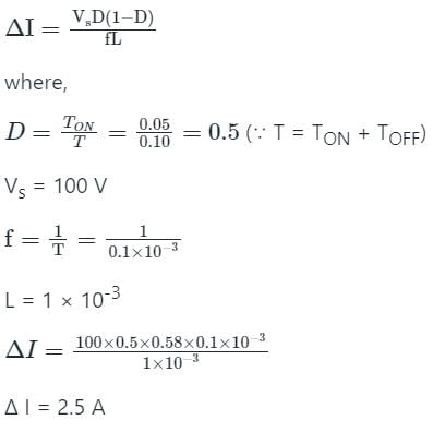
Consider the boost converter of the input voltage to this converter is 6 V. The average output voltage is Vo = 18 V and the average load current Io = 0.4 A. If the switching frequency is 20 kHz for L = 250 μH, then the ripple current of inductor is _______A.
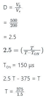
A step-up dc chopper has input dc voltage of 200 V and average output voltage 500 V. If the conduction time of the switch is 150 μs, determine the pulse width of the output voltage.
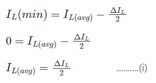
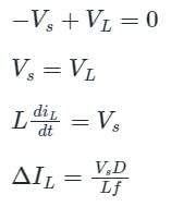
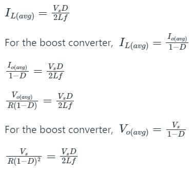
The minimum inductance (Lmin) for continuous current for a boost converter is given by (where D is duty ratio):
A step up chopper delivers an average output voltage of 100 V from an input supply of 60 V when operating with a continuous source current. What is the operating duty ratio for the switch?
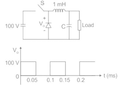
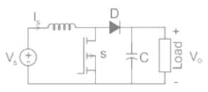
Figure (i) shows the circuit diagram of a chopper. The switch s in the circuit in the figure (i) is switched such that the voltage VD across the diode has the waveshape as shown in the figure (ii). The capacitance C is large so that the voltage across it is constant. If the switch s and diode d are ideal
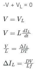
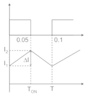
The peak to peak ripple (in A) in the inductor current is-
