Test: Control System - 2 - Electronics and Communication Engineering (ECE) MCQ
20 Questions MCQ Test - Test: Control System - 2

the angle of departure of the root locus at s = —1 + j is
The open-loop transfer function of a system is  . The root locus of the system is
The open-loop transfer function of a system is G(s) = Indicate the correct root locus diagram is
A negative feedback control system has a transfer function G(s)
compensator Gc(s) = in order to achieve zero steady state error for a step input. Select 'a' and 'k' so that the overshoot to a step is approximately 5% and the settling time (with a 2% criterion) is approximately 1 second.
The transfer function of a lead compensator is Gc s = . The maximum phase shift that can be obtained from this compensator is
Calculate the sensitivity of the closed-loop system shown in figure below with respect to the forward path transfer function at w = 1.3 rad/sec.
The magnitude plot of a transfer function is shown in figure below. The transfer function is
The open-loop transfer function of a feedback system is
The gain margin of the system is___
The open-loop transfer function of a feedback system is G (s)H (s) =
The value of gain k for obtaining a gain margin of 3 dB for stable system is_________
In the figure given below the phase margin and the gain margin are:
A LTI system is characterized by the homogeneous state equation The initial state is
The state transition matrix 4(t) is
The state equation in the phase canonical form can be obtained from the transfer function by:
Consider the system shown in figure below and investigate whether it is observable or not.
For a (-)ve feedback second order control system in its step response, the maximum value of the output response in time domain form is given by
Q. The damping factor (damping coefficient) of this system is
For a (-)ve feedback second order control system in its step response, the maximum value of the output response in time domain form is given by
Q. The open-loop zero frequency gain of this given unity feedback control system equals to
The block diogram of a feedback system is shown in figure (a).
Q. Find the minimum value of G for which the step response of the system would
exhibit an overshoot as shown in figure (b).
The block diogram of a feedback system is shown in figure (a).
Q. For G equal to twice this minimum value, find the time period 't' indicated in figure (b).
The system shown in figure below has the oscillation of 2.5 rad/sec, and there are no poles in right half of s-plane.
Q. Also find the value of P.
Consider a unity gain closed-loop transfer function with forward path gain,

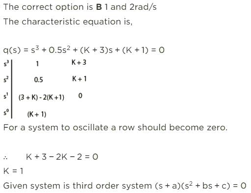
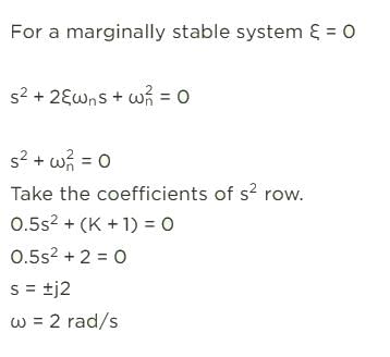
If the system is producing undamped oscillations, then value of K and corresponding frequency of oscillations are respectively


