Electrical Engineering (EE) Exam  >  Electrical Engineering (EE) Tests  >  Test: Power Electronics & Drives- 1 - Electrical Engineering (EE) MCQ

Test: Power Electronics & Drives- 1 - Electrical Engineering (EE) MCQ


Test Description

10 Questions MCQ Test - Test: Power Electronics & Drives- 1

Test: Power Electronics & Drives- 1 for Electrical Engineering (EE) 2024 is part of Electrical Engineering (EE) preparation. The Test: Power Electronics & Drives- 1 questions and answers have been prepared according to the Electrical Engineering (EE) exam syllabus.The Test: Power Electronics & Drives- 1 MCQs are made for Electrical Engineering (EE) 2024 Exam. Find important definitions, questions, notes, meanings, examples, exercises, MCQs and online tests for Test: Power Electronics & Drives- 1 below.
Solutions of Test: Power Electronics & Drives- 1 questions in English are available as part of our course for Electrical Engineering (EE) & Test: Power Electronics & Drives- 1 solutions in Hindi for Electrical Engineering (EE) course. Download more important topics, notes, lectures and mock test series for Electrical Engineering (EE) Exam by signing up for free. Attempt Test: Power Electronics & Drives- 1 | 10 questions in 30 minutes | Mock test for Electrical Engineering (EE) preparation | Free important questions MCQ to study for Electrical Engineering (EE) Exam | Download free PDF with solutions
Test: Power Electronics & Drives- 1 - Question 1

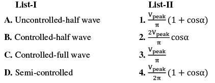
Match List-I (1-ϕ Rectifier topology - feeding resistive load) with List-II (Average output voltage) and select the correct answer: (α is the firing angle)
Test: Power Electronics & Drives- 1 - Question 2

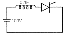
The latching current in the below circuit is 4 mA. The  minimum width of the gate pulse required to turn on the thyristor is 
Detailed Solution for Test: Power Electronics & Drives- 1 - Question 2

1 Crore+ students have signed up on EduRev. Have you? Download the App
Test: Power Electronics & Drives- 1 - Question 3

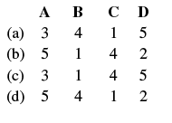
Match List-I (Waveforms) with List-II (Descriptions) and select the correct answer:

List 1:

A. 
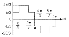
B. 

C. 

D. 

List-II

1. Single phase fully controlled ac to dc converter

2. Voltage commutated dc to dc chopper with input dc voltage E

3. Phase voltage of a three phase inverter with 180° conduction and input dc voltage E

4. Line voltage of a three phase inverter with 120° conduction and input dc voltage E

5. Three-phase diode bridge rectifier 


Test: Power Electronics & Drives- 1 - Question 4

A single phase ac voltage controller  feeding a pure resistance  load has a load voltage of 200 V(rms) when fed from a source  of 250 V(rms). The input power factor of the controller is  

Detailed Solution for Test: Power Electronics & Drives- 1 - Question 4

Test: Power Electronics & Drives- 1 - Question 5

In a thyristor-controlled rectifier, the firing  angle of thyristor  is to be controlled in the range of  

Test: Power Electronics & Drives- 1 - Question 6

A 3-phase wound rotor induction motor is controlled by a  chopper-controlled resistance in its rotor circuit. A resistance  of 2Ω is connected in the rotor circuit and a resistance of 4Ω is additionally  connected during OFF periods of the chopper.  The OFF period of the chopper is 4 ms. The average  resistance in the rotor  circuit for the chopper frequency of   200 Hz is  

Detailed Solution for Test: Power Electronics & Drives- 1 - Question 6

Chopper frequency = 200 Hz
Time period of chopper (T) = 1/200 = 5 ms

Chopper OFF period = 4 ms

Test: Power Electronics & Drives- 1 - Question 7

The most suitable device for high frequency inversion in  SMPS is  

Detailed Solution for Test: Power Electronics & Drives- 1 - Question 7

MOSFETs have the lowest switching
losses so they are the most suitable devices
for the SMPS.

Test: Power Electronics & Drives- 1 - Question 8

In a self-controlled synchronous motor fed from a variable frequency inverter

Test: Power Electronics & Drives- 1 - Question 9

in case of voltage source inverter, freewheeling diode can be avoided for the load of

Test: Power Electronics & Drives- 1 - Question 10

A single-phase full-bridge converter with a free-wheeling  diode feeds an inductive load. The load resistance is 15.53Ω and it has a large inductance providing constant and ripple  free d.c. current. Input to converter is from an ideal 230V,  50Hz single phase source. For a firing delay  angle of 60°, the  average value of diode current is  

Detailed Solution for Test: Power Electronics & Drives- 1 - Question 10

V0 for a single-phase full-bridge converter
with a free-wheeling diode

Information about Test: Power Electronics & Drives- 1 Page
In this test you can find the Exam questions for Test: Power Electronics & Drives- 1 solved & explained in the simplest way possible. Besides giving Questions and answers for Test: Power Electronics & Drives- 1, EduRev gives you an ample number of Online tests for practice

Top Courses for Electrical Engineering (EE)

Download as PDF

Top Courses for Electrical Engineering (EE)