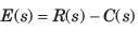
Test: Time Response - Electronics and Communication Engineering (ECE) MCQ
20 Questions MCQ Test - Test: Time Response

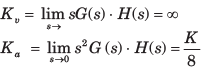
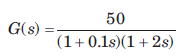
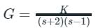
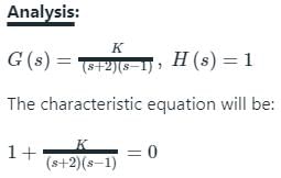
The open-loop transfer function of a ufb control system is
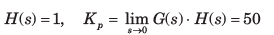
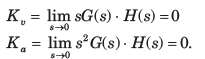
The position, velocity and acceleration error constants are respectively
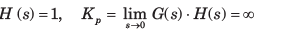
The open-loop transfer function of a unit feedback system is
The position, velocity and acceleration errorconstants are respectively

If a type 0 system is subjected to step input, what is its effect on steady state error?
The forward-path transfer function of a unity negative feedback system is given by:
The value of K which will place both the poles of the closed-loop system at the same location is.
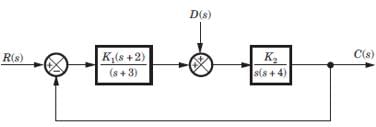
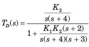
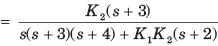
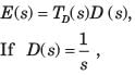
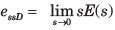
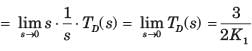
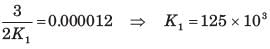
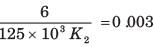
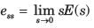
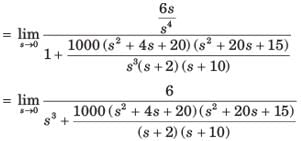
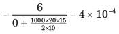
For the system shown in fig.the steady state error component due to unit step disturbance is 0.000012 and steady state error component due to unit ramp input is 0.003. The values of K1 and K2 are respectively

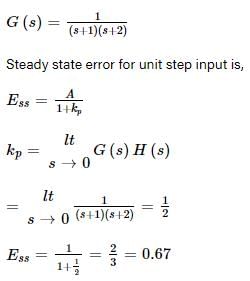
The transfer function for a single loop nonunity feedback control system is
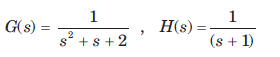
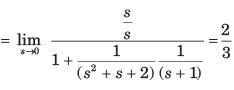
The steady state error due to unit step input is
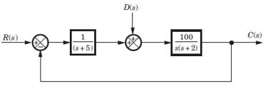
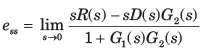
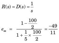
For the system of fig. the total steady state error due to a unit step input and a unit step disturbance is
 and
and 
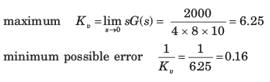
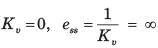
The forward path transfer function of a ufb system is
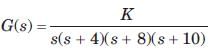
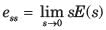
If a unit ramp is applied, the minimum possiblesteady-state error is
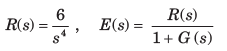
The forward-path transfer function of a ufb system is
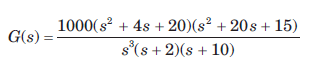
The system has r(t) = t3 applied to its input. Thesteady state error is
Consider a unity feedback system with forward transfer function given by
The steady-state error in the output of the system for a unit-step input is _________ (up to 2 decimal places).
A system has position error constant Kp = 3. The steady state error for input of 8tu(t) is
The forward path transfer function of a unity feedback system is
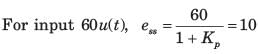
For input of 60u(t) steady state error is
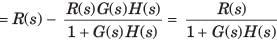
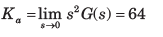
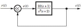
For ufb system shown in fig. the transfer function is
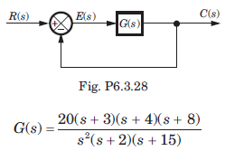
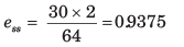
If input is 30t2 , then steady state error is
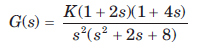
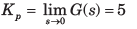
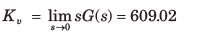
The forward-path transfer function of a ufb control system is
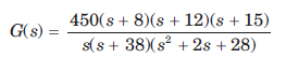
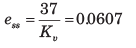
The steady state errors for the test input 37tu(t) is
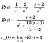
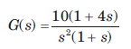
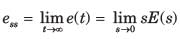
In the system shown in fig. r(t) = 1 + 2t , t > 0. The steady state error e(t) is equal to
A ufb control system has a forward path transfer function
If the system is subjected to an input r(t) = 1 + t + 1/2 t2 , t > 0the steady state error of the system will be
The system shown in fig. has steady-state error 0.1 to unit step input. The value of K is
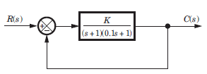
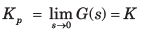
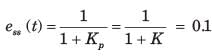

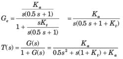
Block diagram of a position control system is shown in fig.
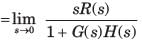
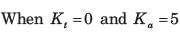
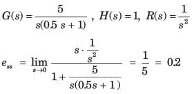
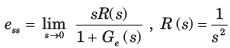
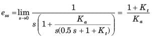
If Kt = 0 and Ka= 5, then the steady state error tounit ramp input is
Block diagram of a position control system is shown in fig.
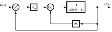
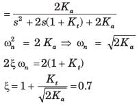
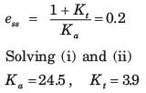
If the damping ratio of the system is increased to 0.7 without affecting the steady state error, then thevalue of Ka and Kt are
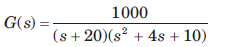
A system has the following transfer function
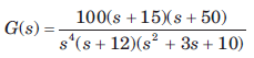
The type and order of the system are respectively
Important Questions for Time Response
Time Response MCQs with Answers
Online Tests for Time Response
|
© EduRev
|
Education Revolution
|


|


within 7 days!