Electronics and Communication Engineering (ECE) Exam  >  Electronics and Communication Engineering (ECE) Tests  >  Test: Combinational Logic Circuits - 1 - Electronics and Communication Engineering (ECE) MCQ

Test: Combinational Logic Circuits - 1 - Electronics and Communication Engineering (ECE) MCQ


Test Description

20 Questions MCQ Test - Test: Combinational Logic Circuits - 1

Test: Combinational Logic Circuits - 1 for Electronics and Communication Engineering (ECE) 2024 is part of Electronics and Communication Engineering (ECE) preparation. The Test: Combinational Logic Circuits - 1 questions and answers have been prepared according to the Electronics and Communication Engineering (ECE) exam syllabus.The Test: Combinational Logic Circuits - 1 MCQs are made for Electronics and Communication Engineering (ECE) 2024 Exam. Find important definitions, questions, notes, meanings, examples, exercises, MCQs and online tests for Test: Combinational Logic Circuits - 1 below.
Solutions of Test: Combinational Logic Circuits - 1 questions in English are available as part of our course for Electronics and Communication Engineering (ECE) & Test: Combinational Logic Circuits - 1 solutions in Hindi for Electronics and Communication Engineering (ECE) course. Download more important topics, notes, lectures and mock test series for Electronics and Communication Engineering (ECE) Exam by signing up for free. Attempt Test: Combinational Logic Circuits - 1 | 20 questions in 60 minutes | Mock test for Electronics and Communication Engineering (ECE) preparation | Free important questions MCQ to study for Electronics and Communication Engineering (ECE) Exam | Download free PDF with solutions
Test: Combinational Logic Circuits - 1 - Question 1

A switching function of four variable, f (w, x y, z) is to equal the product of two other function f1 and f2, of the same variable f = f1f2 . The function f and f1 are as follows :

f = ∑m(4,7,15)

f = ∑m(0,1,2, 3, 4,7, 8,9,10,11,15)

Que: The number of full specified function, that will satisfy the given condition, is

Detailed Solution for Test: Combinational Logic Circuits - 1 - Question 1

f = ∑m(4,7,15)

f1 = ∑m(0,1,2, 3, 4,7, 8,9,10,11,15)

f2 = ∑m(4,7,15) + ∑dc(5, 6, 12, 13, 14)

There are 5 don't care condition. So 25 = 32 different functions f2 

Test: Combinational Logic Circuits - 1 - Question 2

A switching function of four variable, f (w, x y, z) is to equal the product of two other function f1 and f2, of the same variable f = f1f2 . The function f and f1 are as follows :

f = ∑m(4,7,15)

f1 = ∑m(0,1,2, 3, 4,7, 8,9,10,11,15)

Que: The simplest function for f2 is

Detailed Solution for Test: Combinational Logic Circuits - 1 - Question 2

1 Crore+ students have signed up on EduRev. Have you? Download the App
Test: Combinational Logic Circuits - 1 - Question 3

A four-variable switching function has minterms mand m9. If the literals in these minterms are complemented, the corresponding minterm numbers are

Detailed Solution for Test: Combinational Logic Circuits - 1 - Question 3

Test: Combinational Logic Circuits - 1 - Question 4

The minimum function that can detect a “divisible by 3’’ 8421 BCD code digit (representation D8 D4 D2 D1 ) is given by

Detailed Solution for Test: Combinational Logic Circuits - 1 - Question 4

0, 3, 6 and 9 are divisible by 3

f = 

Test: Combinational Logic Circuits - 1 - Question 5

Detailed Solution for Test: Combinational Logic Circuits - 1 - Question 5

Test: Combinational Logic Circuits - 1 - Question 6

For a binary half subtractor having two input A and B, the correct set of logical expressions for the outputs D = (A - B) and X (borrow) are

Detailed Solution for Test: Combinational Logic Circuits - 1 - Question 6

Test: Combinational Logic Circuits - 1 - Question 7

Detailed Solution for Test: Combinational Logic Circuits - 1 - Question 7

Test: Combinational Logic Circuits - 1 - Question 8

What type of logic circuit is represented by the figure shown below?

digital-circuits-questions-answers-combinational-circuits-q2

Detailed Solution for Test: Combinational Logic Circuits - 1 - Question 8

After solving the circuit we get (A’B’)+AB as output, which is XNOR operation. Thus, it will produce 1 when inputs are even number of 1s or all 0s, and produce 0 when input is odd number of 1s.

Test: Combinational Logic Circuits - 1 - Question 9

The building block shown in fig. is a active high output decoder.

Que: The output X is

Detailed Solution for Test: Combinational Logic Circuits - 1 - Question 9

Test: Combinational Logic Circuits - 1 - Question 10

The building block shown in fig. is a active high output decoder.

Que: The output Y is

Detailed Solution for Test: Combinational Logic Circuits - 1 - Question 10

Test: Combinational Logic Circuits - 1 - Question 11

A logic circuit consist of two 2 x 4 decoder as shown in fig.

The output of decoder are as follow

The value of f ( x, y, z) is

Detailed Solution for Test: Combinational Logic Circuits - 1 - Question 11

Test: Combinational Logic Circuits - 1 - Question 12

Number of 2 × 1 Multiplexers are required to implement 64 × 1 Multiplexers

Detailed Solution for Test: Combinational Logic Circuits - 1 - Question 12

A 64 × 1 multiplexer has 64 inputs so if we use 2 × 1 multiplexers 32 are needed in the first stage for 64 inputs, the output of these 32 multiplexers are connected to inputs of 16 multiplexers in the second stage.

Similarly, in third stage, 8 (2 × 1) multiplexers are used, in fourth stage 4 are used and finally 2 (2 × 1) multiplexers in the fifth stage, 1 in the sixth stage.

Total 2 × 1 multiplexers needed are 32 + 16 + 8 + 4 + 2 + 1 = 63


Test: Combinational Logic Circuits - 1 - Question 13

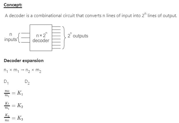
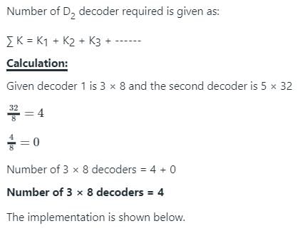
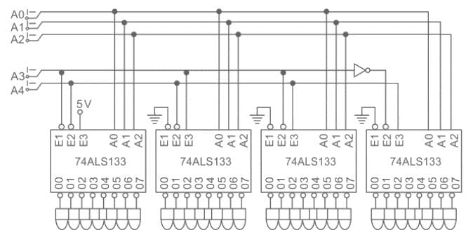
How many 3-line-to-8-line decoders are required for a 5-of-32 decoder?

Detailed Solution for Test: Combinational Logic Circuits - 1 - Question 13


Test: Combinational Logic Circuits - 1 - Question 14

Number of 2 × 1 Multiplexers are required to implement 64 × 1 Multiplexers

Detailed Solution for Test: Combinational Logic Circuits - 1 - Question 14

A 64 × 1 multiplexer has 64 inputs so if we use 2 × 1 multiplexers 32 are needed in the first stage for 64 inputs, the output of these 32 multiplexers are connected to inputs of 16 multiplexers in the second stage.

Similarly, in third stage, 8 (2 × 1) multiplexers are used, in fourth stage 4 are used and finally 2 (2 × 1) multiplexers in the fifth stage, 1 in the sixth stage.

Total 2 × 1 multiplexers needed are 32 + 16 + 8 + 4 + 2 + 1 = 63

Test: Combinational Logic Circuits - 1 - Question 15

The network shown in fig. implements

Detailed Solution for Test: Combinational Logic Circuits - 1 - Question 15

Test: Combinational Logic Circuits - 1 - Question 16

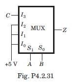
The MUX shown in fig. P4.2.31 is 4 * 1 multiplexer. The output Z is
Detailed Solution for Test: Combinational Logic Circuits - 1 - Question 16

Correct Answer :- c

Explanation : Z = (bar AB)C + (bar A)B + (bar B)A + AB

= (bar A)[(barB)C + B) + A[(bar B) + B]

= (bar A)[(B + C)] + A

= A + B + C

Test: Combinational Logic Circuits - 1 - Question 17

The output of the 4 x 1 multiplexer shown in fig. is

Test: Combinational Logic Circuits - 1 - Question 18

The MUX shown in fig. is a 4 x 1 multiplexer. The output Z is

Detailed Solution for Test: Combinational Logic Circuits - 1 - Question 18

Test: Combinational Logic Circuits - 1 - Question 19

Detailed Solution for Test: Combinational Logic Circuits - 1 - Question 19

The output from the upper first level multiplexer is fa and from the lower first level multiplexer is fb

Test: Combinational Logic Circuits - 1 - Question 20

For the logic circuit shown in fig.the output Y is

Detailed Solution for Test: Combinational Logic Circuits - 1 - Question 20

Information about Test: Combinational Logic Circuits - 1 Page
In this test you can find the Exam questions for Test: Combinational Logic Circuits - 1 solved & explained in the simplest way possible. Besides giving Questions and answers for Test: Combinational Logic Circuits - 1, EduRev gives you an ample number of Online tests for practice

Top Courses for Electronics and Communication Engineering (ECE)

Download as PDF

Top Courses for Electronics and Communication Engineering (ECE)