Mechanical Engineering Exam  >  Mechanical Engineering Tests  >  Test: Design of Joint - 1 - Mechanical Engineering MCQ

Test: Design of Joint - 1 - Mechanical Engineering MCQ


Test Description

20 Questions MCQ Test - Test: Design of Joint - 1

Test: Design of Joint - 1 for Mechanical Engineering 2024 is part of Mechanical Engineering preparation. The Test: Design of Joint - 1 questions and answers have been prepared according to the Mechanical Engineering exam syllabus.The Test: Design of Joint - 1 MCQs are made for Mechanical Engineering 2024 Exam. Find important definitions, questions, notes, meanings, examples, exercises, MCQs and online tests for Test: Design of Joint - 1 below.
Solutions of Test: Design of Joint - 1 questions in English are available as part of our course for Mechanical Engineering & Test: Design of Joint - 1 solutions in Hindi for Mechanical Engineering course. Download more important topics, notes, lectures and mock test series for Mechanical Engineering Exam by signing up for free. Attempt Test: Design of Joint - 1 | 20 questions in 60 minutes | Mock test for Mechanical Engineering preparation | Free important questions MCQ to study for Mechanical Engineering Exam | Download free PDF with solutions
Test: Design of Joint - 1 - Question 1

Square key of side "d/4" each and length l is used to transmit torque "T" from the shaft of diameter "d" to the hub of a pulley. Assuming the length of the key to be equal to the thickness of the pulley, the average shear stress developed in the key is given by    

Detailed Solution for Test: Design of Joint - 1 - Question 1

If a square key of sides d/4 is used then. In that case, for shear failure we
have 

 [Where τx is the yield stress in shear and l is the key length.]

Test: Design of Joint - 1 - Question 2

A 60 mm long and 6 mm thick fillet weld carries a steady load of 15 kNalong the weld. The shear strength of the weld material is equal to 200MPa. The factor of safety is  

Detailed Solution for Test: Design of Joint - 1 - Question 2

1 Crore+ students have signed up on EduRev. Have you? Download the App
Test: Design of Joint - 1 - Question 3

Assertion (A): A cotter joint is used to rigidly connect two coaxial rods carrying tensile load.

Reason (R): Taper in the cotter is provided to facilitate its removal when it fails due to shear.  

Detailed Solution for Test: Design of Joint - 1 - Question 3

A cotter is a flat wedge shaped piece of rectangular cross-section and its width is tapered (either on one side or both sides) from one end to another for an easy adjustment. The taper varies from 1 in 48 to 1 in 24 and it may be increased up to 1 in 8, if a locking device is provided. The locking device may be a taper pin or a set screw used on the lower end of the cotter. The cotter is usually made of mild steel or wrought iron. A cotter joint is a temporary fastening and is used to connect rigidly two co-axial rods or bars which are subjected to axial tensile or compressive forces.

Test: Design of Joint - 1 - Question 4

Match List I with List II and select the correct answer using the code given below the Lists:

Test: Design of Joint - 1 - Question 5

In a gib and cotter joint, the gib and cotter are subjected to       

Detailed Solution for Test: Design of Joint - 1 - Question 5

Test: Design of Joint - 1 - Question 6

In a cotter joint, the width of the cotter at the centre is 50 mm and its thickness is 12 mm. The load acting on the cotter is 60 kN. What is the shearing stress developed in the cotter? 

Detailed Solution for Test: Design of Joint - 1 - Question 6

It is a case of double shear.


Test: Design of Joint - 1 - Question 7

Match List-l (Machine element) with List-II (Cause of failure) and select the correct answer using the codes given below the lists:         

Detailed Solution for Test: Design of Joint - 1 - Question 7

• In machinery, the general term “shaft” refers to a member, usually of circular cross-section, which supports gears, sprockets, wheels, rotors, etc., and which is subjected to torsion and to transverse or axial loads acting singly or in combination.

• An “axle” is a non-rotating member that supports wheels, pulleys, and carries no torque.

• A “spindle” is a short shaft. Terms such as line-shaft, head-shaft, stub shaft, transmission shaft, countershaft, and flexible shaft are names associated with special usage. 

Test: Design of Joint - 1 - Question 8

A cotter joint is used when no relative motion is permitted between the rods joined by the cotter. It is capable of transmitting  

Test: Design of Joint - 1 - Question 9

Assertion (A): When the coupler of a turn buckle is turned in one direction both the connecting rods either move closer or move away from each other depending upon the direction of rotation of the coupler.    

Reason (R): A turn buckle is used to connect two round rods subjected to tensile loading and requiring subsequent adjustment for tightening or loosening. 

Detailed Solution for Test: Design of Joint - 1 - Question 9

Test: Design of Joint - 1 - Question 10

A spur gear transmitting power is connected to the shaft with a key of rectangular section. The type (s) of stresses developed in the key is fare. 

Detailed Solution for Test: Design of Joint - 1 - Question 10

Key develops both shear and bearing stresses.

Test: Design of Joint - 1 - Question 11

Which key is preferred for the condition where a large amount of impact torque is to be transmitted in both direction of rotation? 

Test: Design of Joint - 1 - Question 12

A square key of side d/4 is to be fitted on a shaft of diameter d and in the hub of a pulley. If the material of the key and shaft is same and the two are to be equally strong in shear, what is the length of the key?   

Test: Design of Joint - 1 - Question 13

A pulley is connected to a power transmission shaft of diameter d by means of a rectangular sunk key of width wand length ‘l’. The width of the key is taken as d/4. For full power transmission, the shearing strength of the key is equal to the torsional shearing strength of the shaft. The ratio of the length of the key to the diameter of the shaft (l/d) is    

Detailed Solution for Test: Design of Joint - 1 - Question 13

Test: Design of Joint - 1 - Question 14

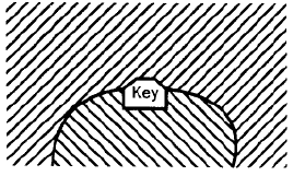
The key shown in the above figure is a 

Test: Design of Joint - 1 - Question 15

The shearing area of a key of length 'L', breadth 'b' and depth 'h' is equal to   

Test: Design of Joint - 1 - Question 16

In a fillet welded joint, the weakest area of the weld is  

Test: Design of Joint - 1 - Question 17

Two metal plates of thickness ’t’ and width 'w' are joined by a fillet weld of 45° as shown in given figure.

When subjected to a pulling force 'F', the stress induced in the weld will be  

Test: Design of Joint - 1 - Question 18

In the welded joint shown in the given figure, if the weld at B has thicker fillets than that at A, then the load carrying capacity P, of the joint will             

Test: Design of Joint - 1 - Question 19

The following two figures show welded joints (x x x x x indicates welds), for the same load and same dimensions of plate and weld. 

The joint shown in

Detailed Solution for Test: Design of Joint - 1 - Question 19

Figure II is better because the weld is in tension and safe stress of weld in tension is greater than shear. 

Test: Design of Joint - 1 - Question 20

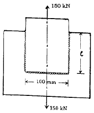
Two plates are joined together by means of single transverse and double parallel fillet welds as shown in figure given above. If the size of fillet is 5 mm and allowable shear load per mm is 300 N, what is the approximate length of each parallel fillet?                  
Detailed Solution for Test: Design of Joint - 1 - Question 20

300 × (100+ 2l) = 15000 or l = 200

Information about Test: Design of Joint - 1 Page
In this test you can find the Exam questions for Test: Design of Joint - 1 solved & explained in the simplest way possible. Besides giving Questions and answers for Test: Design of Joint - 1, EduRev gives you an ample number of Online tests for practice

Top Courses for Mechanical Engineering

Download as PDF

Top Courses for Mechanical Engineering