NEET Exam  >  NEET Tests  >  Physics: Topic-wise Test- 5 - NEET MCQ

Physics: Topic-wise Test- 5 - NEET MCQ


Test Description

30 Questions MCQ Test - Physics: Topic-wise Test- 5

Physics: Topic-wise Test- 5 for NEET 2024 is part of NEET preparation. The Physics: Topic-wise Test- 5 questions and answers have been prepared according to the NEET exam syllabus.The Physics: Topic-wise Test- 5 MCQs are made for NEET 2024 Exam. Find important definitions, questions, notes, meanings, examples, exercises, MCQs and online tests for Physics: Topic-wise Test- 5 below.
Solutions of Physics: Topic-wise Test- 5 questions in English are available as part of our course for NEET & Physics: Topic-wise Test- 5 solutions in Hindi for NEET course. Download more important topics, notes, lectures and mock test series for NEET Exam by signing up for free. Attempt Physics: Topic-wise Test- 5 | 45 questions in 45 minutes | Mock test for NEET preparation | Free important questions MCQ to study for NEET Exam | Download free PDF with solutions
Physics: Topic-wise Test- 5 - Question 1

Two infinitely long conducting parallel rails are connected through a capacitor C as shown in the figure. A conductor of length l is moved with constant speed v0. Which of the following graph truly depicts the variation of current through the conductor with time ?

Detailed Solution for Physics: Topic-wise Test- 5 - Question 1

By Faraday's Law of induction,
ε=− dϕ​/dt
=−Bl (dx/dt) ​=−Blv0​
This emf should induce the movement of charges creating a current. But due to the attached capacitor, all charges are conserved.
Thus I= dq/dt ​=0
The correct option is C.

Physics: Topic-wise Test- 5 - Question 2

A conducting rod moves with constant velocity v perpendicular to the long, straight wire carrying a current I as shown compute that the emf generated between the ends of the rod.


Detailed Solution for Physics: Topic-wise Test- 5 - Question 2

The magnetic field near the conducting rod due to long current carrying wire is 
B= μ0​I/2πr ​ (using Ampere's law, ∫B.dl=μ0​I)
Now, induced emf due to moving rod is e=Blv= (μ0​I/2πr) ​×lv= μ0​vIl/2πr

1 Crore+ students have signed up on EduRev. Have you? Download the App
Physics: Topic-wise Test- 5 - Question 3

The effective value of current i = 2 sin 100p t + 2 sin (100pt + 30º) is

Detailed Solution for Physics: Topic-wise Test- 5 - Question 3

cosθ=sin(90o−θ)
sinα+sinβ=2sin (α+β/2)​cos (α−β​/2)
i=2sin100πt+2cos(100πt+30o)
=2sin100πt+2sin(90o−(100πt+30o))
=2sin100πt+2sin(60o−100πt)
=2 x 2 x sin [{(100−100)πt+60o }/2] x cox[(100+100)πt−60o/2]
​=4 x sin30o∗cos(100πt−30o)
=4x(1/2) x cos(100πt−30o)
=2cos(100πt−30o)
therefore, Io​=2A
Irms​=2 / √2​= √2​A

Physics: Topic-wise Test- 5 - Question 4

The magnetic field due to current element depends upon which of the following factors:

Detailed Solution for Physics: Topic-wise Test- 5 - Question 4

From Biot-Savart law, magnetic field at a point p, B= (μ0​/4π)∫ [(Idl×r​)/ r3]
where r is the distance of point p from conductor and I is the current in the conductor.
Thus magnetic field due to current carrying conductor depends on the current flowing through conductor and distance from the conductor and length of the conductor.
 

Physics: Topic-wise Test- 5 - Question 5

A circular loop of radius 0.0157 m carries a current of 2 A. The magnetic field at the centre of the loop is​

Detailed Solution for Physics: Topic-wise Test- 5 - Question 5

The magnetic field due to a circular loop is given by:
B= μ0​​2πi​/4πr
=10−7×2π×2/0.0157 ​
=8×10⁻⁵ Wb/m2

Physics: Topic-wise Test- 5 - Question 6

Along an infinitely long conductor carrying a current of 8 A we keep another conductor of length 5 m carrying a current of 3 A. Both the conductors are 10 cm apart. Find the force on small conductor.​

Detailed Solution for Physics: Topic-wise Test- 5 - Question 6

I1=3A
I2=8A
l=5m
r=0.1m
F=?
Force per unit length on the small conductor is given by:
f= μo2I1I2/4πr
Total force on the length of small conductor is
F=fl
F= μo2I1I2 l/4πr
F=4πx10-7x2x3x8x5/4π x 0.1
F=2.4x10⁻⁴N

Physics: Topic-wise Test- 5 - Question 7

We use _________ to find the direction of force when two current carrying conductors are kept parallel to each other.

Detailed Solution for Physics: Topic-wise Test- 5 - Question 7

The direction of force (motion) of a current carrying conductor in a magnetic field is given by Fleming’s left hand rule. 
It states that ‘ If we hold the thumb, fore finger and middle finger of the left hand perpendicular to each other such that the fore finger points in the direction of magnetic field, the middle finger points in the direction of current, then the thumb shows the direction of force (motion) of the conductor.
 

Physics: Topic-wise Test- 5 - Question 8

In an iron cored coil the iron core is removed so that the coil becomes an air cored coil. The inductance of the coil will

Detailed Solution for Physics: Topic-wise Test- 5 - Question 8

In an iron cored coil the iron core is removed so that the coil becomes an air cored coil. The inductance of the coil will decrease.

Physics: Topic-wise Test- 5 - Question 9

The magnetic flux through a stationary loop with resistance R varies during interval of time T as f = at (T _ t). The heat generated during this time neglecting the inductance of loop will be

Detailed Solution for Physics: Topic-wise Test- 5 - Question 9

E=dx/dt =d(a(Tt-t2))/dt=a(T-2t)
I=E/R=a(T-2t)/R
Heat liberated,
△k=I2Rdt


=(a2 /R)[T2t+(4t3/3)-2Tt2]T0
=△H=a2T3/3R

Physics: Topic-wise Test- 5 - Question 10

The dimensions of permeability of free space can be given by

Detailed Solution for Physics: Topic-wise Test- 5 - Question 10

In SI units, permeability is measured in Henries per meter H/m or Hm−1.
Henry has the dimensions of [ML2T−2A−2].
Dimensions for magnetic permeability will be [ML2T−2A−2]/[L]=[MLT−2A−2]

Physics: Topic-wise Test- 5 - Question 11

A closed planar wire loop of area A and arbitrary shape is placed in a uniform magnetic field of magnitude B, with its plane perpendicular to magnetic field. The resistance of the wire loop is R. The loop is now turned upside down by 180° so that its plane again becomes perpendicular to the magnetic field. The total charge that must have flowen through the wire ring in the process is

Detailed Solution for Physics: Topic-wise Test- 5 - Question 11

Induced emf= d(flux)/dt​=R[dq​/dt]
⇒Δq= Δ(flux)​/R=2BA/R​

Physics: Topic-wise Test- 5 - Question 12

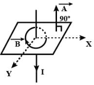
A square coil ABCD is placed in x-y plane with its centre at origin. A long straight wire, passing through origin, carries a current in negative z-direction. Current in this wire increases with time.The induced current in the coil is

Detailed Solution for Physics: Topic-wise Test- 5 - Question 12

As magnetic field lines due to current carrying wire is along the surface and hence,
ϕ=B.A=BAcos90O=0

Physics: Topic-wise Test- 5 - Question 13

In the arrangement shown in given figure current from A to B is increasing in magnitude. Induced current in the loop will

Detailed Solution for Physics: Topic-wise Test- 5 - Question 13

The direction of the induced current is as shown in the figure, according to Lenz’s law which states that the indeed current flows always in such a direction as to oppose the change which is giving rise to it.

Physics: Topic-wise Test- 5 - Question 14

The north pole of a magnet is brought near a coil. The induced current in the coil as seen by an observer on the side of magnet will be

Detailed Solution for Physics: Topic-wise Test- 5 - Question 14

The direction of the current will be anticlockwise.
 
According to Lenz's law, the current in the coil will be induced in the direction that'll oppose the external magnetic field .
As the flux due to the external magnet is increasing ( as the N-pole is brought close ) , the coil will have to induce current in the anticlockwise direction to oppose this increase in flux and not in clockwise direction as that'll end up supporting the external flux.

Physics: Topic-wise Test- 5 - Question 15

A metal sheet is placed in a variable magnetic field which is increasing from zero to maximum. Induced current flows in the directions as shown in figure. The direction of magnetic field will be -

Detailed Solution for Physics: Topic-wise Test- 5 - Question 15

The direction of these circular magnetic lines is dependent upon the direction of current. The density of the induced magnetic field is directly proportional to the magnitude of the current. Direction of the circular magnetic field lines can be given by Maxwell's right hand grip rule or Right handed cork screw rule.

Physics: Topic-wise Test- 5 - Question 16

A small conducting rod of length l, moves with a uniform velocity v in a uniform magnetic field B as shown in fig-

Detailed Solution for Physics: Topic-wise Test- 5 - Question 16

The rod is moving towards the right in a field directed into the page.
Now, if we apply Fleming's right hand rule, then the direction of induced current will be from end X to end Y.
But, according to Lenz's law the emf induced in the rod will be such that it opposes the motion of the rod.
Hence, the actual emf induced will be from end Y to end X. So, the current will also flow from end Y to end X.
Now, using the convention of current end Y should be positive and end X should be negative.
So, correct answer is option b

Physics: Topic-wise Test- 5 - Question 17

The magnetic flux through a surface varies with time as follows:

= 12t2 + 7t + 3
here, is in milliweber and t is in seconds.
What will be the induced emf at t = 5s?​

Detailed Solution for Physics: Topic-wise Test- 5 - Question 17

Given :
            ϕ=12t2+7t+C
where, C is a constant, t is in sec, ϕ in milli-weber
The induced e.m.f. in the loop at t=5, on differentiating the equation with respect to 't'.
          dtdϕ​=dtd​(12t2+7t+C)
                =24t+7
 at            t=5
                dtdϕ​=24×(5)+7
                          =120+7
                          =127 mV
 

Physics: Topic-wise Test- 5 - Question 18

In Faraday’s experiment if the magnet is moved towards the coil, it results in ____________ in magnetic field B at any point on the wire loop. The _________ shows deflection. Thus emf is induced by changing B.

Detailed Solution for Physics: Topic-wise Test- 5 - Question 18

Initailly the loop taken have no current or no magnetic field associated with it when the magnet moved towards the loop the galvanometer show deflection showing the presence of current and current moving in loop also has magnetic field around it
 

Physics: Topic-wise Test- 5 - Question 19

What is the value of induced e.m.f if a wire is moved between the gap of two poles of a magnetin in 1 s and magnetic flux between the poles is 6 x 10⁻³ Wb?​

Detailed Solution for Physics: Topic-wise Test- 5 - Question 19

The correct answer is B.To calculate the induced e.m.f when a wire is moved between the gap of two poles of a magnet, we can use Faraday's Law of electromagnetic induction.

Calculation:

- Given magnetic flux, Φ = 6 x 10^-3 Wb
- Time taken, t = 1 s

Formula:

The induced e.m.f can be calculated using the formula:

E = -ΔΦ/Δt

Substitute the given values:

E = - (6 x 10^-3 Wb) / (1 s)
E = - 6 x 10^-3 V
E = 6 mV

Therefore, the value of induced e.m.f when a wire is moved between the gap of two poles of a magnet in 1s is 6 mV.

Physics: Topic-wise Test- 5 - Question 20

Two similar circular co-axial loops carry equal current in the same direction. If the loops be brought nearer, the currents in them will

Detailed Solution for Physics: Topic-wise Test- 5 - Question 20

When the two loops are brought together, the flux linking the two loops increases. By Lenz's law a current will be induced such that it opposes this change of flux . Therefore to oppose the increase in flux, the current in the two loops will decrease, so the flux decreases.

Physics: Topic-wise Test- 5 - Question 21

When a wire loop is rotated in a magnetic field, the direction of induced emf changes once in each

Detailed Solution for Physics: Topic-wise Test- 5 - Question 21

Flux of the magnetic field through the loop
ϕ=B.Acosωt
Emf= −dϕ/dt​=B.Aωsinωt
ωt=0 to π,  sinωt=+ve
ωt=π to2 π,  sinωt=−ve
Hence, the direction of induced e.m.f. changes once in 1/2​ revolution.
 

Physics: Topic-wise Test- 5 - Question 22

An a.c. circuit consists of an inductor of inductances 0.5 H and a capacitor of capacitance 8 mF in series. The current in the circuit is maximum when the angular frequency of an a.c. source is

Detailed Solution for Physics: Topic-wise Test- 5 - Question 22

Given,
Inductance and capacitance are joined in series, and inductance L=0.5H,
And capacitance C=8μF=8×10⁻⁶F.
We know that,
ω=1/√(LC)
ω=1/√(8×10−6×0.5)=1/(2×10−3)=0.5×103HZ=500HZ

Physics: Topic-wise Test- 5 - Question 23

The rms value of an AC of 50 Hz is 10 amp. The time taken by an alternating current in reaching from zero to maximum value and the peak value will be ;

Detailed Solution for Physics: Topic-wise Test- 5 - Question 23

Time taken by alternating current to reach maximum from zero is 4T​.
where T is the time period of the AC function.
T=1/f​, Frequency (f)=50 Hz.
So time taken to reach maximum=T/4​=1/4f​=1/(4×50)​=5×10−3 sec
IRMS​=​I0/√2​, I0​=Peak value of current.
Peak value of current I0​=√2​×IRMS​=√2​×10=14.14 A
 

Physics: Topic-wise Test- 5 - Question 24

A voltage of peak value 283 V varying frequency is applied to a series L-C-R combination in which R = 3W; L = 25 mH and C = 400 mF. Then, the frequency (in Hz) of the source at which maximum power is dissipated in the above, is

Detailed Solution for Physics: Topic-wise Test- 5 - Question 24

Here, V0​=283V,R=3Ω,L=25×10−3H
C=400μF=4×10⁻⁴F
Maximum power is dissipated at resonance, for which 
 
ν=1/[2π√(LC)]​​= (1×7​)/[2×22(25×10−3×4×10−4)]
=(7×10³​)/(44√10​)
=50.3Hz

Physics: Topic-wise Test- 5 - Question 25

An ac-circuit having supply voltage E consists of a resistor of resistance 3W and an inductor of reactance 4W as shown in the figure. The voltage across the inductor at t = p/w is


Detailed Solution for Physics: Topic-wise Test- 5 - Question 25

Here,
XL = 4 Ω
R = 3 Ω
Z = √(XL2 + R2)=√(42 + 32)
  = 5 Ω
E0 = 10 V
In the LR circuit current in the ckt is given by
I = (E0/Z)sin(ωt - Φ)
Φ = tan-1(XL/R)
=>  Φ = tan-1(4/3)
I = (E0/Z)sin(ωt - Φ)
  = (10/5) sin(ωt - Φ)
I at t = T/2
  = 2sin(ωT/2 – Φ)
 =  2sin(π - Φ)
  = 2sin(tan-1(4/3))
  = 2×0.8
  = 1.6 A
Potential difference across the resistor = 1.6×R
   = 1.6×3
   = 4.8 V
Potential difference across the inductor = 1.6XL
      = 1.6×4 = 6.4 V

Physics: Topic-wise Test- 5 - Question 26

 When 100 V DC is applied across a solenoid a current of 1A flows in it. When 100 V AC is applied across the same coil, the current drops to 0.5 A. If the frequency of the AC source is 50 Hz, the impedance and inductance of the solenoid are :

Detailed Solution for Physics: Topic-wise Test- 5 - Question 26

Impedance= Vac/Iac​ ​​=100V/0.5A ​=200Ω
R= Vdc​​/Idc ​ =100/1​=100Ω
Lω =√ (impedance2−R2​)=√(2002−1002​)=173.2
L=173.2/ ω​= 173.2/2π50​=0.55H
 

Physics: Topic-wise Test- 5 - Question 27

 In the circuit shown if the emf of source at an instant is 5V, the potential difference across capacitor at the same instant is 4V. The potential difference across R at that instant may be


Detailed Solution for Physics: Topic-wise Test- 5 - Question 27

Physics: Topic-wise Test- 5 - Question 28

Let f = 50 Hz, and C = 100 mF in an AC circuit containing a capacitor only. If the peak value of the current in the circuit is 1.57 A at t = 0. The expression for the instantaneous voltage across the capacitor will be

Detailed Solution for Physics: Topic-wise Test- 5 - Question 28

Peak value of voltage
V0=i0XC =i0/2πvC
=>1.57/(2x3.14x50x100x10-6)
Hence if equation of current i = io sin ω t then in capacitive circuit voltage is 
V=V0 (ωt -  π/2)
=>50[sin2π x50t- (π/2)]
 =50[100πt-(π/2)]


Physics: Topic-wise Test- 5 - Question 29

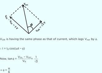
The given figure represents the phasor diagram of a series LCR circuit connected to an ac source. At the instant t' when the source voltage is given by V = V0coswt, the current in the circuit will be


Detailed Solution for Physics: Topic-wise Test- 5 - Question 29

Given: V=V0cosωt

Here,


∴I=I0cos(ωt−π/6)

Physics: Topic-wise Test- 5 - Question 30

 Power factor of an L-R series circuit is 0.6 and that of a C_R series circuit is 0.5. If the element (L, C, and R) of the two circuits are joined in series the power factor of this circuit is found to be 1. The ratio of the resistance in the L-R circuit to the resistance in the C-R circuit is

Detailed Solution for Physics: Topic-wise Test- 5 - Question 30

cosϕ1=0.6=5/3
tanϕ1=4/3= XC/R2…(1)
cosϕ1=0.5=1/2
tanϕ2=√3= R2/XC…(2)
From (1) and (2)3√3/4=R1/R2

View more questions
Information about Physics: Topic-wise Test- 5 Page
In this test you can find the Exam questions for Physics: Topic-wise Test- 5 solved & explained in the simplest way possible. Besides giving Questions and answers for Physics: Topic-wise Test- 5, EduRev gives you an ample number of Online tests for practice

Top Courses for NEET

Download as PDF

Top Courses for NEET