Electrical Engineering (EE) Exam  >  Electrical Engineering (EE) Tests  >  Test: Analog Electronics - 1 - Electrical Engineering (EE) MCQ

Test: Analog Electronics - 1 - Electrical Engineering (EE) MCQ


Test Description

25 Questions MCQ Test - Test: Analog Electronics - 1

Test: Analog Electronics - 1 for Electrical Engineering (EE) 2024 is part of Electrical Engineering (EE) preparation. The Test: Analog Electronics - 1 questions and answers have been prepared according to the Electrical Engineering (EE) exam syllabus.The Test: Analog Electronics - 1 MCQs are made for Electrical Engineering (EE) 2024 Exam. Find important definitions, questions, notes, meanings, examples, exercises, MCQs and online tests for Test: Analog Electronics - 1 below.
Solutions of Test: Analog Electronics - 1 questions in English are available as part of our course for Electrical Engineering (EE) & Test: Analog Electronics - 1 solutions in Hindi for Electrical Engineering (EE) course. Download more important topics, notes, lectures and mock test series for Electrical Engineering (EE) Exam by signing up for free. Attempt Test: Analog Electronics - 1 | 25 questions in 25 minutes | Mock test for Electrical Engineering (EE) preparation | Free important questions MCQ to study for Electrical Engineering (EE) Exam | Download free PDF with solutions
Test: Analog Electronics - 1 - Question 1

To prevent a DC return between source and load, it is necessary to use

Detailed Solution for Test: Analog Electronics - 1 - Question 1

Capacitor offers infinite impedance to DC.

Test: Analog Electronics - 1 - Question 2

For a base current of 10 μA, what is the value of collector current in common emitter if βdc = 100

Detailed Solution for Test: Analog Electronics - 1 - Question 2

IC = 10 x 100 μA = 1 mA.

1 Crore+ students have signed up on EduRev. Have you? Download the App
Test: Analog Electronics - 1 - Question 3

Which of the following oscillators is suitable for frequencies in the range of mega hertz?

Detailed Solution for Test: Analog Electronics - 1 - Question 3

Only LC oscillators are suitable for MHz range.

Test: Analog Electronics - 1 - Question 4

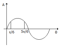
If the input to the ideal comparator shown in the figure is a sinusoidal signal of 8 V (peak to peak) without any DC component, then the output of the comparator has a duty cycle of

Detailed Solution for Test: Analog Electronics - 1 - Question 4

Test: Analog Electronics - 1 - Question 5

A half wave diode circuit using ideal diode has an input voltage 20 sin ωt volts. Then average and rms values of output voltage are

Detailed Solution for Test: Analog Electronics - 1 - Question 5

and VC = 0.5 x 20 = 10 V.

Test: Analog Electronics - 1 - Question 6

An RC coupled amplifier has an open loop gain of 200 and a lower cutoff frequency of 50 Hz. If negative feedback with β = 0.1 is used, the lower cut off frequency will be

Detailed Solution for Test: Analog Electronics - 1 - Question 6

New lower cutoff frequency = .

Test: Analog Electronics - 1 - Question 7

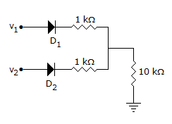
In figure v1 = 8 V and v2 = 4 V. Which diode will conduct?
Detailed Solution for Test: Analog Electronics - 1 - Question 7

D1 will conduct and the output voltage will be about 7 V. Therefore D2 will be reverse biased and will not conduct.

Test: Analog Electronics - 1 - Question 8

The load impedance ZL of a CE amplifier has R and L in series. The phase difference between output and input will be

Detailed Solution for Test: Analog Electronics - 1 - Question 8

It is 180º for purely resistive load and between 180º and 270ºor R-L load.

Test: Analog Electronics - 1 - Question 9

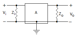
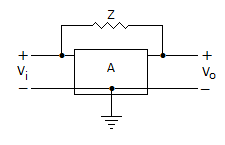
Gain of the amplifier is 'A'. Then the I/P impedance and O/P impedance of the closed loop amplifier shown below would be
Detailed Solution for Test: Analog Electronics - 1 - Question 9

By using Miller theorem circuit can be redrawn as

.

Test: Analog Electronics - 1 - Question 10

If an amplifier with gain of - 1000 and feedback factor β = - 0.1 had a gain change of 20% due to temperature, the change in gain of the feedback amplifier would be

Detailed Solution for Test: Analog Electronics - 1 - Question 10

As we know, Gain with feedback

A = - 1000, β = -0.1 .

Test: Analog Electronics - 1 - Question 11

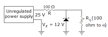
In figure The minimum and maximum load currents are

Detailed Solution for Test: Analog Electronics - 1 - Question 11

When RL = ∞, IL = 0,

When RL = 100 Ω, or 120 mA.

Test: Analog Electronics - 1 - Question 12

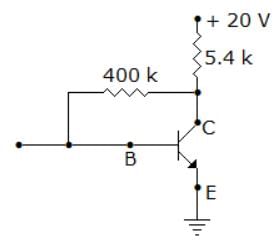
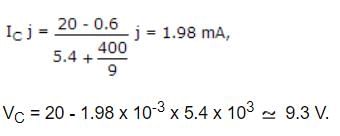
In figure, VEB = 0.6 V, β = 99. Then VC and IC are

Detailed Solution for Test: Analog Electronics - 1 - Question 12

Test: Analog Electronics - 1 - Question 13

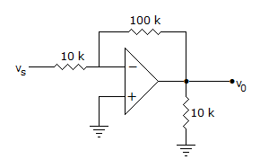
The input impedance of op-amp circuit of figure is

Detailed Solution for Test: Analog Electronics - 1 - Question 13

Due to the presence of virtual ground at input, the resistance in the series path of input of inverting amplifier is input impedance.

Test: Analog Electronics - 1 - Question 14

In a BJT circuit a pnp transistor is replaced by npn transistor. To analyse the new circuit

Detailed Solution for Test: Analog Electronics - 1 - Question 14

All voltages and currents have reverse polarity.

Test: Analog Electronics - 1 - Question 15

To protect the diodes in a rectifier and capacitor input filter circuit it is necessary to use

Detailed Solution for Test: Analog Electronics - 1 - Question 15

Resistor reduces surge current.

Test: Analog Electronics - 1 - Question 16

The output V0 in figure is

Detailed Solution for Test: Analog Electronics - 1 - Question 16

Input to non-inverting op-amp is -10 x 10-6 x 103 = -10 mV.

Therefore output = = -100 mV.

Test: Analog Electronics - 1 - Question 17

In a CE amplifier the input impedance is equal to the ratio of

Detailed Solution for Test: Analog Electronics - 1 - Question 17

Input is applied to base with emitter grounded. The input impedance is the ratio of ac base voltage to ac base current.

Test: Analog Electronics - 1 - Question 18

For a system to work, as oscillator the total phase shift of the loop gain must be equal to

Detailed Solution for Test: Analog Electronics - 1 - Question 18

Gain of system with + ve feedback = for oscillation

but V0 ≠ 0

so, that 1 - AB = 0 AB = 1 ∠0ºor 360º.

Test: Analog Electronics - 1 - Question 19

An amplifier has a large ac input signal. The clipping occurs on both the peaks. The output voltage will be nearly a

Detailed Solution for Test: Analog Electronics - 1 - Question 19

When a sinusoidal voltage is clipped on both sides it resembles a square wave.

Test: Analog Electronics - 1 - Question 20

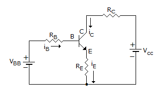
The transistor of following figure in Si diode with a base current of 40 μA and ICBO = 0, if VBB = 6V, RE = 2 kΩ and β = 90, IBQ = 20 μA then RB =
Detailed Solution for Test: Analog Electronics - 1 - Question 20

.

Test: Analog Electronics - 1 - Question 21

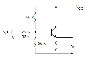
In the amplifier circuit of figure hfe = 100 and hie = 1000 Ω. The voltage gain of amplifier is about
Detailed Solution for Test: Analog Electronics - 1 - Question 21

.

Test: Analog Electronics - 1 - Question 22

The efficiency of a full wave rectifier using centre tapped transformer is twice that in full wave bridge rectifier.

Detailed Solution for Test: Analog Electronics - 1 - Question 22

Efficiency of full wave rectifier with centre tapped transformer is slightly higher than that of bridge rectifier.

Test: Analog Electronics - 1 - Question 23

Assertion (A): CE amplifier is the most widely used BJT amplifier

Reason (R): CE amplifier has zero phase difference between input and output

Detailed Solution for Test: Analog Electronics - 1 - Question 23

There is 180� phase difference between input and output.

Test: Analog Electronics - 1 - Question 24

Assertion (A): For large signal variations an amplifier circuit has to be analysed graphically

Reason (R): The output characteristics of a transistor is nonlinear.

Detailed Solution for Test: Analog Electronics - 1 - Question 24

Since the characteristics is non-linear, graphical analysis is needed.

Test: Analog Electronics - 1 - Question 25

Negative feedback reduces noise originating at the amplifier input.

Detailed Solution for Test: Analog Electronics - 1 - Question 25

It has no effect on noise originating at amplifier input.

Information about Test: Analog Electronics - 1 Page
In this test you can find the Exam questions for Test: Analog Electronics - 1 solved & explained in the simplest way possible. Besides giving Questions and answers for Test: Analog Electronics - 1, EduRev gives you an ample number of Online tests for practice

Top Courses for Electrical Engineering (EE)

Download as PDF

Top Courses for Electrical Engineering (EE)