Electrical Engineering (EE) Exam  >  Electrical Engineering (EE) Tests  >  Test: Analog Electronics - 3 - Electrical Engineering (EE) MCQ

Test: Analog Electronics - 3 - Electrical Engineering (EE) MCQ


Test Description

25 Questions MCQ Test - Test: Analog Electronics - 3

Test: Analog Electronics - 3 for Electrical Engineering (EE) 2024 is part of Electrical Engineering (EE) preparation. The Test: Analog Electronics - 3 questions and answers have been prepared according to the Electrical Engineering (EE) exam syllabus.The Test: Analog Electronics - 3 MCQs are made for Electrical Engineering (EE) 2024 Exam. Find important definitions, questions, notes, meanings, examples, exercises, MCQs and online tests for Test: Analog Electronics - 3 below.
Solutions of Test: Analog Electronics - 3 questions in English are available as part of our course for Electrical Engineering (EE) & Test: Analog Electronics - 3 solutions in Hindi for Electrical Engineering (EE) course. Download more important topics, notes, lectures and mock test series for Electrical Engineering (EE) Exam by signing up for free. Attempt Test: Analog Electronics - 3 | 25 questions in 25 minutes | Mock test for Electrical Engineering (EE) preparation | Free important questions MCQ to study for Electrical Engineering (EE) Exam | Download free PDF with solutions
Test: Analog Electronics - 3 - Question 1

A full wave rectifier circuit using centre tapped transformer and a bridge rectifier are fed at 100 V, 50 Hz. The frequencies of outputs in these two rectifiers are

Detailed Solution for Test: Analog Electronics - 3 - Question 1

Output wave in each case has two cycles for one cycle of input wave.

Test: Analog Electronics - 3 - Question 2

When the ac base voltage in a CE amplifier circuit is too high, the ac emitter current is

Detailed Solution for Test: Analog Electronics - 3 - Question 2

A high signal causes distortion because v-i characteristics of BJT is non-linear.

1 Crore+ students have signed up on EduRev. Have you? Download the App
Test: Analog Electronics - 3 - Question 3

When load is coupled to class A amplifier through transformer, efficiency decreases.

Detailed Solution for Test: Analog Electronics - 3 - Question 3

Transformer coupling increases efficiency.

Test: Analog Electronics - 3 - Question 4

The gain of an FET amplifier can be changed by changing

Detailed Solution for Test: Analog Electronics - 3 - Question 4

Gain is proportional to gm .

Test: Analog Electronics - 3 - Question 5

The open loop gain of an actual op-amp is about 100.

Detailed Solution for Test: Analog Electronics - 3 - Question 5

It is very high.

Test: Analog Electronics - 3 - Question 6

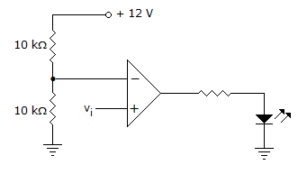
In the circuit figure LED will be on when v1 is

Detailed Solution for Test: Analog Electronics - 3 - Question 6

Voltage input to inverting input is . Therefore, vi should be more than 6 V.

Test: Analog Electronics - 3 - Question 7

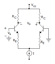
A differential amplifier consists of two CB amplifiers.

Detailed Solution for Test: Analog Electronics - 3 - Question 7

It consists of two CE amplifiers.

Test: Analog Electronics - 3 - Question 8

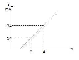
Figure shows a portion of linear v - i characteristics of diode. If applied voltage is + 6 V, the current will be
Detailed Solution for Test: Analog Electronics - 3 - Question 8

.

Test: Analog Electronics - 3 - Question 9

A power transistor dissipates 5 W. If ambient temperature is 30º and case to air thermal resistance is 10º C/W, the case temperature is

Detailed Solution for Test: Analog Electronics - 3 - Question 9

Test: Analog Electronics - 3 - Question 10

An R-C coupled amplifier has mid-frequency gain of 200 and a frequency response from 100 Hz to 20 kHz. A negative feedback network with β = 0.2 is incorporated into the amplifier circuit, the Bandwidth will be

Detailed Solution for Test: Analog Electronics - 3 - Question 10

B.W. = fH' - fL' .

Test: Analog Electronics - 3 - Question 11

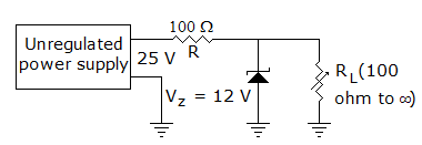
In figure the zener current

Detailed Solution for Test: Analog Electronics - 3 - Question 11

When IL = 0, Zener current = 130 mA, when IL = 120 mA, zener current (t = 10 mA).

Test: Analog Electronics - 3 - Question 12

In a commercially available good power supply the voltage regulation is about

Detailed Solution for Test: Analog Electronics - 3 - Question 12

A good power supply does not allow output voltage to vary by more than 1% .

Test: Analog Electronics - 3 - Question 13

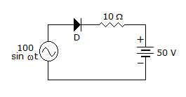
In the circuit of figure the diode

Detailed Solution for Test: Analog Electronics - 3 - Question 13

Diode will always be reverse biased.

Test: Analog Electronics - 3 - Question 14

The most commonly used bias in BJT amplifier circuits is

Detailed Solution for Test: Analog Electronics - 3 - Question 14

Voltage divider bias stabilizes IC.

Test: Analog Electronics - 3 - Question 15

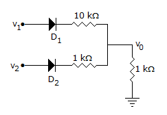
In the circuit of figure, v1 = v2 = 10 V. Then

Detailed Solution for Test: Analog Electronics - 3 - Question 15

Current in diode D2 will be more because resistance in series with D2 is less.

Test: Analog Electronics - 3 - Question 16

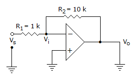
The inverting op-amp shown in the figure has an open loop gain to 100. The closed loop given is

Detailed Solution for Test: Analog Electronics - 3 - Question 16

Applying KCL inverting node

.

Test: Analog Electronics - 3 - Question 17

In a voltage regulated power supply the zener operates in the breakdown region when (Vin is input voltage and Vz is zener breakdown voltage)

Detailed Solution for Test: Analog Electronics - 3 - Question 17

Zener breakdown when input voltage is more than zener breakdown voltage.

Test: Analog Electronics - 3 - Question 18

The parameter h11 for CB circuit is higher than that for CE circuit.

Detailed Solution for Test: Analog Electronics - 3 - Question 18

It is lower.

Test: Analog Electronics - 3 - Question 19

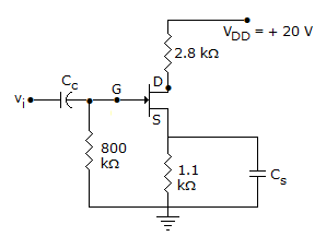
Figure shows a self bias circuit for FET amplifier, ID = 4 mA. Then IS =
Detailed Solution for Test: Analog Electronics - 3 - Question 19

Since gate current is negligible IS = ID = 4 mA.

Test: Analog Electronics - 3 - Question 20

In the CE equivalent circuit of figure, the voltage gain is
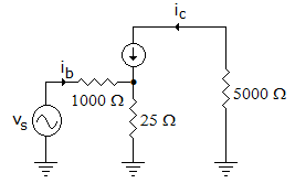
Detailed Solution for Test: Analog Electronics - 3 - Question 20

Test: Analog Electronics - 3 - Question 21

In a CE amplifier

Detailed Solution for Test: Analog Electronics - 3 - Question 21

Since ac collector resistance is less than dc collector resistance, slope of ac load line is more than that of dc load line.

Test: Analog Electronics - 3 - Question 22

The voltage gain of an amplifier without and with feedback are 100 and 20. The negative feedback is

Detailed Solution for Test: Analog Electronics - 3 - Question 22

or β = 0.04 or 4% .

Test: Analog Electronics - 3 - Question 23

In the circuit shown in figure, RC = 10k, RE = 150Ω, β = 100, I = 1 mA. The value of , will be

Detailed Solution for Test: Analog Electronics - 3 - Question 23

circuit shown is Darlington Amplifier.

Gain

.

Test: Analog Electronics - 3 - Question 24

Calculate the conductivity of pure silicon at room temperature when the concentration of carriers is 1.6 x 10¹⁰ per cm3. Take μe = 1500 cm2/V-sec, μh = 500 cm2/V-sec at room temperature,

Detailed Solution for Test: Analog Electronics - 3 - Question 24

σi = (μe + μn) . e . ni .

Test: Analog Electronics - 3 - Question 25

A potential of 7 V is applied to a silicon diode. A resistance of 1 kΩ is also connected in series. If the diode is forward biased, the current in the circuit is

Detailed Solution for Test: Analog Electronics - 3 - Question 25

A = 6.3 mA.

Information about Test: Analog Electronics - 3 Page
In this test you can find the Exam questions for Test: Analog Electronics - 3 solved & explained in the simplest way possible. Besides giving Questions and answers for Test: Analog Electronics - 3, EduRev gives you an ample number of Online tests for practice

Top Courses for Electrical Engineering (EE)

Download as PDF

Top Courses for Electrical Engineering (EE)