Electrical Engineering (EE) Exam  >  Electrical Engineering (EE) Tests  >  Test: Power Electronics - 7 - Electrical Engineering (EE) MCQ

Test: Power Electronics - 7 - Electrical Engineering (EE) MCQ


Test Description

25 Questions MCQ Test - Test: Power Electronics - 7

Test: Power Electronics - 7 for Electrical Engineering (EE) 2024 is part of Electrical Engineering (EE) preparation. The Test: Power Electronics - 7 questions and answers have been prepared according to the Electrical Engineering (EE) exam syllabus.The Test: Power Electronics - 7 MCQs are made for Electrical Engineering (EE) 2024 Exam. Find important definitions, questions, notes, meanings, examples, exercises, MCQs and online tests for Test: Power Electronics - 7 below.
Solutions of Test: Power Electronics - 7 questions in English are available as part of our course for Electrical Engineering (EE) & Test: Power Electronics - 7 solutions in Hindi for Electrical Engineering (EE) course. Download more important topics, notes, lectures and mock test series for Electrical Engineering (EE) Exam by signing up for free. Attempt Test: Power Electronics - 7 | 25 questions in 25 minutes | Mock test for Electrical Engineering (EE) preparation | Free important questions MCQ to study for Electrical Engineering (EE) Exam | Download free PDF with solutions
Test: Power Electronics - 7 - Question 1

Assertion (A): SUS is a PUT and avalanche diode connected between gate and cathode

Reason (R): SBS has two SUS inbuilt together and connected in anti-parallel

Test: Power Electronics - 7 - Question 2

In a single phase full wave controlled rectifier using centre tap transformer, the voltage across each half of secondary is Vm sin ωt. The peak inverse voltage is

1 Crore+ students have signed up on EduRev. Have you? Download the App
Test: Power Electronics - 7 - Question 3

Which statement is correct?

Test: Power Electronics - 7 - Question 4

In a three phase series inverter, the firing frequency is

Test: Power Electronics - 7 - Question 5

A 3 phase fully controlled converter is a

Test: Power Electronics - 7 - Question 6

In a half bridge inverter the gate pulses of the two thyristors have a phase displacement of

Test: Power Electronics - 7 - Question 7

A fully controlled bridge converter can operate in quadrants

Test: Power Electronics - 7 - Question 8

A class E chopper

Test: Power Electronics - 7 - Question 9

A cycloconverter uses

Test: Power Electronics - 7 - Question 10

Assertion (A): A fully controlled bridge converter can operate in first and fourth quadrant.

Reason (R): A semi converter is cheaper than a full converter.

Test: Power Electronics - 7 - Question 11

The commutation method in an inverter, is

Test: Power Electronics - 7 - Question 12

Inverters find applications in

Test: Power Electronics - 7 - Question 13

When a thyristor is conducting, the voltage drop across it is about

Test: Power Electronics - 7 - Question 14

The use of free wheeling diode in controlled rectifier improves the waveshape of load current.

Test: Power Electronics - 7 - Question 15

As the firing of a thyristor is delayed, the output voltage of a controlled rectifier decreases.

Test: Power Electronics - 7 - Question 16

Assertion (A): A GTO can be turned on and turned off by gate pulses

Reason (R): A GTO can be turned off by negative gate pulse.

Test: Power Electronics - 7 - Question 17

In a half bridge inverter circuit fed by a battery of voltage V, the rms value of fundamental component of output voltage is

Test: Power Electronics - 7 - Question 18

In a full bridge single phase inverter feeding RLC load

Test: Power Electronics - 7 - Question 19

It is possible to use a freewheeling diode in

Test: Power Electronics - 7 - Question 20

Assertion (A): When the anode current of an SCR starts increasing during turn on process, the anode cathode voltage drop starts decreasing.

Reason (R): During turn on the reverse biased junction in SCR breaksdown.

Test: Power Electronics - 7 - Question 21

In a certain inverter circuit each thyristor carries 26.67 A for 60º, 13.33 A for 120º and zero A for 180º of the cycle. The rms current of thyristor is

Test: Power Electronics - 7 - Question 22

The factor η for a UJT is about

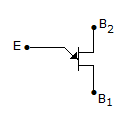
Test: Power Electronics - 7 - Question 23

The symbol in figure is for

Test: Power Electronics - 7 - Question 24

In a single phase full converter fed by a source having inductance, the number of thyristors conducting during overlap is

Test: Power Electronics - 7 - Question 25

The cut in voltages for germanium and silicon diodes respectively as

Information about Test: Power Electronics - 7 Page
In this test you can find the Exam questions for Test: Power Electronics - 7 solved & explained in the simplest way possible. Besides giving Questions and answers for Test: Power Electronics - 7, EduRev gives you an ample number of Online tests for practice

Top Courses for Electrical Engineering (EE)

Download as PDF

Top Courses for Electrical Engineering (EE)