


All Exams >
Computer Science Engineering (CSE) >
6 Months Preparation for GATE CSE >
All Questions
All questions of Combinational Circuits for Computer Science Engineering (CSE) Exam
3 bits full adder contains ________- a)3 combinational inputs
- b)4 combinational inputs
- c)6 combinational inputs
- d)8 combinational inputs
Correct answer is option 'D'. Can you explain this answer?
3 bits full adder contains ________
a)
3 combinational inputs
b)
4 combinational inputs
c)
6 combinational inputs
d)
8 combinational inputs
|
|
Anshu Mehta answered |
Explanation:
A full adder is a combinational circuit that is used to perform addition of two binary numbers along with a carry input. It takes three inputs - two bits to be added (A and B) and a carry input (Cin). The output of a full adder consists of two bits - Sum (S) and Carry-out (Cout).
A 3-bit full adder is a circuit that can perform addition of three 3-bit numbers. It takes three sets of inputs - A0, B0, Cin for the least significant bit, A1, B1, Cin for the middle bit, and A2, B2, Cin for the most significant bit.
Inputs:
A 3-bit full adder has a total of 9 inputs: 3 inputs for each bit.
- A0, A1, A2 are the inputs for the first number's bits.
- B0, B1, B2 are the inputs for the second number's bits.
- Cin is the carry input.
Outputs:
A 3-bit full adder produces three sets of outputs: Sum (S0, S1, S2) and Carry-out (Cout).
- S0, S1, S2 are the outputs for the sum of the corresponding bits.
- Cout is the carry-out from the most significant bit.
Combination:
The number of combinational inputs is the sum of the number of inputs required for each bit. In this case, there are 3 bits, so the total number of combinational inputs is:
3 (inputs for A) + 3 (inputs for B) + 1 (carry input) = 7
However, we need to include the carry-out from the previous bit as well. Since there are 3 bits, we need to consider the carry-out from the second bit for the third bit's addition. Therefore, the total number of combinational inputs is:
7 (inputs for A, B, and Cin) + 1 (carry-out from the previous bit) = 8
Hence, the correct answer is option D) 8 combinational inputs.

What is a multiplexer?- a)It is a type of decoder which decodes several inputs and gives one output
- b)A multiplexer is a device which converts many signals into one
- c)It takes one input and results into many output
- d)It is a type of encoder which decodes several inputs and gives one output
Correct answer is option 'B'. Can you explain this answer?
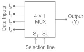
What is a multiplexer?
a)
It is a type of decoder which decodes several inputs and gives one output
b)
A multiplexer is a device which converts many signals into one
c)
It takes one input and results into many output
d)
It is a type of encoder which decodes several inputs and gives one output
|
|
Milan Rane answered |
A multiplexer, also known as a mux, is a device used in digital circuits to combine multiple input signals into a single output signal. It is commonly used in communication systems, digital data processing, and various other applications. The correct answer to the question is option 'B', which states that a multiplexer is a device that converts many signals into one.
Here is a detailed explanation of why option 'B' is the correct answer:
What is a multiplexer?
A multiplexer is a digital circuit that selects one of many input signals and forwards it to a single output line. It is often represented with the symbol "MUX". The selection of the input signal is controlled by a set of control signals, known as select lines.
Working Principle
The working principle of a multiplexer is based on the concept of digital switching. It has multiple input lines, one output line, and select lines. The number of input lines depends on the configuration of the multiplexer. For example, a 4-input multiplexer will have four input lines.
Functionality
The multiplexer works by using the select lines to enable one of the input lines and ignore the others. The selected input signal is then passed through to the output line. The selection process is based on the binary value of the control signals. Each control signal combination corresponds to a specific input line.
Advantages and Applications
- Multiplexers are used in communication systems to combine multiple data streams into one transmission line, thus increasing the efficiency of data transmission.
- They are used in digital data processing to select data from multiple sources and route it to the desired destination.
- Multiplexers can also be used for data storage and retrieval, as they allow multiple inputs to share a single output line.
In conclusion, a multiplexer is a device that combines multiple signals into one output signal. It is widely used in various digital applications and plays a crucial role in improving the efficiency of data transmission and processing.
Number of 2 × 1 Multiplexers are required to implement 64 × 1 Multiplexers- a)60
- b)61
- c)62
- d)63
Correct answer is option 'D'. Can you explain this answer?
Number of 2 × 1 Multiplexers are required to implement 64 × 1 Multiplexers
a)
60
b)
61
c)
62
d)
63
|
|
Avantika Menon answered |
The number 2 is an integer and does not have a numerical value.
DTMF stands for ___________.- a)Dual Tone Magnetic Frequency
- b)Double Tone Magnetic Frequency
- c)Dual Tone Multiple Frequency
- d)Dual Tone Mechanical Frequency
Correct answer is option 'C'. Can you explain this answer?
DTMF stands for ___________.
a)
Dual Tone Magnetic Frequency
b)
Double Tone Magnetic Frequency
c)
Dual Tone Multiple Frequency
d)
Dual Tone Mechanical Frequency
|
|
Partho Joshi answered |
DTMF (Dual Tone Multiple Frequency)
DTMF stands for Dual Tone Multiple Frequency. It is a signaling system used for telephone signaling over analog telephone lines in the voice-frequency band between telephone handsets and other communications devices and switching centers.
How DTMF works
- DTMF assigns a specific frequency (consisting of two separate tones) to each key on the phone keypad.
- When a key is pressed on the phone, it generates a combination of these two frequencies.
- The tones are decoded at the receiving end to determine which key was pressed.
Usage of DTMF
- DTMF is commonly used for interactive voice response systems, in which a user navigates through a menu by pressing keys on their phone.
- It is also used in telephone banking, credit card transactions, and various other automated systems.
Advantages of DTMF
- DTMF is more reliable than pulse dialing systems as it is less prone to errors.
- It allows for faster and more accurate transmission of signals over telephone lines.
Conclusion
In conclusion, DTMF is a widely used signaling system that plays a crucial role in enabling communication and interaction with automated systems over telephone networks. Its reliability, speed, and accuracy make it a preferred choice for various applications in telecommunication.
What is the function of an enable input on a multiplexer chip?- a)To apply Vcc
- b)To connect ground
- c)To active the entire chip
- d)To active one half of the chip
Correct answer is option 'C'. Can you explain this answer?
What is the function of an enable input on a multiplexer chip?
a)
To apply Vcc
b)
To connect ground
c)
To active the entire chip
d)
To active one half of the chip
|
|
Sudhir Patel answered |
Enable input is used to active the chip, when enable is high the chip works (ACTIVE), when enable is low the chip does not work (MEMORY). However, Enable can be Active-High or Active-Low, indicating it is active either when it is connected to VCC or GND respectively.
For the device shown here, assume the D input is LOW, both S inputs are LOW and the input is LOW. What is the status of the Y’ outputs?
- a)All are HIGH
- b)All are LOW
- c)All but Y0 are LOW
- d)All but Y0 are HIGH
Correct answer is option 'D'. Can you explain this answer?
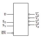
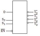
For the device shown here, assume the D input is LOW, both S inputs are LOW and the input is LOW. What is the status of the Y’ outputs?
a)
All are HIGH
b)
All are LOW
c)
All but Y0 are LOW
d)
All but Y0 are HIGH
|
|
Ravi Singh answered |
In the given diagram, S0 and S1 are selection bits. So,
I/P S0 S1 O/P
D = 0 0 0 Y0
D = 0 0 1 Y1
D = 0 1 0 Y2
D = 0 1 1 Y3
Hence, inputs are S0 and S1 are Low means 0, so output is Y0 and rest all are HIGH.
I/P S0 S1 O/P
D = 0 0 0 Y0
D = 0 0 1 Y1
D = 0 1 0 Y2
D = 0 1 1 Y3
Hence, inputs are S0 and S1 are Low means 0, so output is Y0 and rest all are HIGH.
Which of the following represents a number of output lines for a decoder with 4 input lines?- a)15
- b)16
- c)17
- d)18
Correct answer is option 'B'. Can you explain this answer?
Which of the following represents a number of output lines for a decoder with 4 input lines?
a)
15
b)
16
c)
17
d)
18
|
|
Shubham Chaudhary answered |
To answer this question, we need to understand how a decoder works and how many output lines it will have based on the number of input lines.
A decoder is a combinational logic circuit that converts an input code into an output code. It is commonly used to decode binary information and is often used in digital systems, such as computers.
A decoder with 4 input lines will have 2^4 = 16 possible input combinations. Each input combination will correspond to a unique output line in the decoder.
Now, let's go through each option and determine the number of output lines:
a) 15: This option is incorrect because a decoder with 4 input lines will have 16 output lines, not 15.
b) 16: This option is correct. As mentioned earlier, a decoder with 4 input lines will have 16 output lines.
c) 17: This option is incorrect because a decoder with 4 input lines will not have 17 output lines.
d) 18: This option is incorrect because a decoder with 4 input lines will not have 18 output lines.
Therefore, the correct answer is option 'B', which represents 16 output lines for a decoder with 4 input lines.
In summary, the number of output lines for a decoder with 4 input lines is 16.
For a two-input XNOR gate, with the input waveforms as shown below, which output waveform is correct?
- a)d
- b)a
- c)c
- d)b
Correct answer is option 'A'. Can you explain this answer?
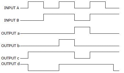
For a two-input XNOR gate, with the input waveforms as shown below, which output waveform is correct?
a)
d
b)
a
c)
c
d)
b
|
|
Sanya Agarwal answered |
When both inputs are same then the o/p is high for a XNOR gate.
i.e., A B O/P
0 0 1
0 1 0
1 0 0
1 1 1.
Thus, it will produce 1 when inputs are even number of 1s or all 0s, and produce 0 when input is odd number of 1s.
i.e., A B O/P
0 0 1
0 1 0
1 0 0
1 1 1.
Thus, it will produce 1 when inputs are even number of 1s or all 0s, and produce 0 when input is odd number of 1s.
Which of the following combinations of logic gates can decode binary 1101?
- a)One 4-input AND gate
- b)One 4-input AND gate, one inverter
- c)One 4-input AND gate, one OR gate
- d)One 4-input NAND gate, one inverter
Correct answer is option 'B'. Can you explain this answer?
Which of the following combinations of logic gates can decode binary 1101?
a)
One 4-input AND gate
b)
One 4-input AND gate, one inverter
c)
One 4-input AND gate, one OR gate
d)
One 4-input NAND gate, one inverter
|
|
Anjana Mishra answered |
Explanation:
To decode binary 1101, we need to determine the combination of logic gates that can produce the output based on the input.
Binary 1101:
The binary number 1101 represents the decimal number 13. In order to decode this binary number, we need to determine the logic gates that can produce an output of 13 based on the input.
Options:
Let's evaluate each option to determine which one can decode binary 1101.
Option a) One 4-input AND gate:
An AND gate produces a high output only when all of its inputs are high. Since we have only one 4-input AND gate, it cannot produce the desired output of 13. Therefore, option a is incorrect.
Option b) One 4-input AND gate, one inverter:
An inverter, also known as a NOT gate, produces the opposite logic level of its input. By using a 4-input AND gate and an inverter, we can create a combination that produces the desired output of 13.
Explanation:
- The 4-input AND gate takes four inputs and produces a high output only when all four inputs are high.
- By connecting the binary inputs to the AND gate, we can ensure that the output will be high only when the binary input is 1101.
- However, the output of the AND gate will be the opposite of what we desire (low instead of high).
- By connecting the output of the AND gate to an inverter, we can invert the logic level and obtain the desired output of high when the input is 1101.
Conclusion:
Option b, which includes a 4-input AND gate and an inverter, is the correct combination of logic gates that can decode binary 1101.
Which of the following is a decoder IC?- a)7890
- b)8870
- c)4047
- d)4041
Correct answer is option 'B'. Can you explain this answer?
Which of the following is a decoder IC?
a)
7890
b)
8870
c)
4047
d)
4041
|
|
Sudhir Patel answered |
8870 is a DTMF decoder circuit, which decodes DTMF tune and produces corresponding output.
Invalid BCD can be made to valid BCD by adding with _______________- a)0101
- b)0110
- c)0111
- d)1001
Correct answer is option 'B'. Can you explain this answer?
Invalid BCD can be made to valid BCD by adding with _______________
a)
0101
b)
0110
c)
0111
d)
1001
|
|
Neha Mishra answered |
Invalid BCD to Valid BCD Conversion
Invalid BCD can be made valid by adding with 0110 (option B).
1. BCD Representation
BCD (Binary Coded Decimal) is a numeric representation where each decimal digit is represented by a 4-bit binary code. The valid BCD digits range from 0000 to 1001, representing the decimal values 0 to 9.
2. Invalid BCD
Invalid BCD refers to a BCD representation that violates the rules of BCD. In BCD, each digit must be in the range of 0000 to 1001. If a digit exceeds this range, it is considered invalid.
3. Adding with 0110
To convert an invalid BCD to a valid BCD, we can add a valid BCD digit to the invalid digit. In this case, adding with 0110 (option B) will make the BCD valid.
4. Explanation
The BCD digits 0000 to 1001 represent the decimal values 0 to 9. Adding any of these valid BCD digits to an invalid BCD digit will bring it back within the valid range.
For example, let's say we have an invalid BCD digit "1011". Adding it with 0110 (option B) gives us:
1 0 1 1 (invalid BCD)
+ 0 1 1 0 (0110)
-----------
1 0 0 0 1 (valid BCD)
The result "10001" is a valid BCD digit representing the decimal value 1.
5. Conclusion
In conclusion, to convert an invalid BCD to a valid BCD, we can add a valid BCD digit to the invalid digit. Adding with 0110 (option B) will ensure that the BCD becomes valid.
What is the indication of a short to ground in the output of a driving gate?- a)Only the output of the defective gate is affected
- b)There is a signal loss to all load gates
- c)The node may be stuck in either the HIGH or the LOW state
- d)The affected node will be stuck in the HIGH state
Correct answer is option 'B'. Can you explain this answer?
What is the indication of a short to ground in the output of a driving gate?
a)
Only the output of the defective gate is affected
b)
There is a signal loss to all load gates
c)
The node may be stuck in either the HIGH or the LOW state
d)
The affected node will be stuck in the HIGH state
|
|
Ravi Singh answered |
Short to ground in the output of a driving gate indicates of a signal loss to all load gates. This results in information being disrupted and loss of data.
How many 3 × 8 line decoders with an enable input line are needed to construct a 6 × 64 line decoder without using any other logic gate?- a)7
- b)8
- c)9
- d)10
Correct answer is option 'C'. Can you explain this answer?
How many 3 × 8 line decoders with an enable input line are needed to construct a 6 × 64 line decoder without using any other logic gate?
a)
7
b)
8
c)
9
d)
10
|
|
Navya Iyer answered |
Understanding the Problem
To construct a 6 × 64 line decoder, we need to decode 6 input bits into 64 output lines. A 3 × 8 line decoder can decode 3 input bits into 8 output lines.
Breaking Down the Requirements
- Inputs: The 6 input lines can be divided into two groups.
- First Group: Utilize 3 bits for the first decoder.
- Second Group: Utilize 3 bits for the second decoder.
Using 3 × 8 Line Decoders
1. First Level Decoding:
- Use 1 decoder for the first 3 input bits.
- This decoder will provide 8 outputs, each corresponding to a unique combination of the first 3 bits.
2. Second Level Decoding:
- Each output of the first decoder can enable one of the 8 second decoders.
- Each of these second decoders will take the remaining 3 bits as input.
- Since there are 8 outputs from the first decoder, we need 8 second decoders.
Total Count of Decoders
- 1 decoder for the first level.
- 8 decoders for the second level.
Final Calculation
By summing the decoders:
- Total decoders = 1 (first level) + 8 (second level) = 9 decoders needed.
Thus, the correct answer is option C: 9.
This arrangement allows decoding of all 6 bits into 64 unique outputs using only 3 × 8 line decoders.
The biggest advantage of ECL is:- a)High fan-out
- b)High speed
- c)Low power consumption
- d)High density
Correct answer is option 'B'. Can you explain this answer?
The biggest advantage of ECL is:
a)
High fan-out
b)
High speed
c)
Low power consumption
d)
High density
|
|
Yash Patel answered |
ECL (Emitter Coupled Logic):
It is fast then all logic family and very high speed in ECL transistor use in differential amplifier configuration
When a transistor is operated in a saturation condition, due to the charge stored in the collector and base regions, it turns ON or OFF slowly. This drawback has been eliminated in ECL by operation the transistor only in the active or off region.
BCD to seven segment conversion is a __________.- a)Decoding process
- b)Encoding process
- c)Comparing process
- d)None of the mentioned
Correct answer is option 'A'. Can you explain this answer?
BCD to seven segment conversion is a __________.
a)
Decoding process
b)
Encoding process
c)
Comparing process
d)
None of the mentioned
|
|
Sudhir Patel answered |
BCD to seven segment code conversion can be treated as a decoding process.
To select 8 inputs, how many data select lines are required?- a)2
- b)3
- c)4
- d)8
Correct answer is option 'B'. Can you explain this answer?
To select 8 inputs, how many data select lines are required?
a)
2
b)
3
c)
4
d)
8
|
|
Sudhir Patel answered |
Concept:
For selecting eight inputs, there are three data select lines that must be used. The multiplexer requires the data select lines. We have three data select lines for eight inputs, and it's an 8:1 multiplexer.
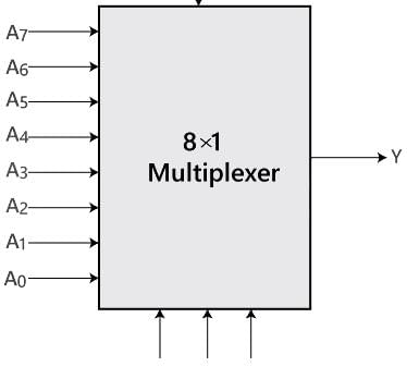
Hence the correct answer is 3.
Hence the correct answer is 3.
How many AND gates are required for a 1-to-8 multiplexer?- a)2
- b)6
- c)5
- d)8
Correct answer is option 'D'. Can you explain this answer?
How many AND gates are required for a 1-to-8 multiplexer?
a)
2
b)
6
c)
5
d)
8
|
|
Isha Deshpande answered |
1-to-8 Multiplexer
A multiplexer is a combinational circuit that selects one of many inputs and directs it to a single output based on the control signals. In a 1-to-8 multiplexer, there are 8 data inputs, one output, and 3 control input lines.
Working of a 1-to-8 Multiplexer
A 1-to-8 multiplexer has 8 data inputs, labeled D0 to D7, and 3 control input lines, labeled A, B, and C. The control input lines determine which data input is selected and passed to the output.
The control input lines can represent 3 binary values: 000, 001, 010, 011, 100, 101, 110, and 111. These binary values can be used to select one of the 8 data inputs.
Implementation of a 1-to-8 Multiplexer using AND gates
To implement a 1-to-8 multiplexer using AND gates, we need to consider the truth table of the multiplexer and derive the logic expressions for the output based on the control input.
The truth table for a 1-to-8 multiplexer is as follows:
| A | B | C | D0 | D1 | D2 | D3 | D4 | D5 | D6 | D7 | Y |
|---|---|---|----|----|----|----|----|----|----|----|---|
| 0 | 0 | 0 | X | X | X | X | X | X | X | X | Y |
| 0 | 0 | 1 | X | X | X | X | X | X | X | X | Y |
| 0 | 1 | 0 | X | X | X | X | X | X | X | X | Y |
| 0 | 1 | 1 | X | X | X | X | X | X | X | X | Y |
| 1 | 0 | 0 | X | X | X | X | X | X | X | X | Y |
| 1 | 0 | 1 | X | X | X | X | X | X | X | X | Y |
| 1 | 1 | 0 | X | X | X | X | X | X | X | X | Y |
| 1 | 1 | 1 | X | X | X | X | X | X | X | X | Y |
From the truth table, we can derive the logic expressions for the output Y as follows:
Y = (A' * B' * C' * D0) + (A' * B' * C * D1) + (A' * B * C' * D2) + (A' * B * C * D3) + (A * B' * C' * D4) + (A * B' * C * D5) +
If the number of n selected input lines is equal to 2^m then it requires _____ select lines.- a)2
- b)m
- c)n
- d)2n
Correct answer is option 'B'. Can you explain this answer?
If the number of n selected input lines is equal to 2^m then it requires _____ select lines.
a)
2
b)
m
c)
n
d)
2n
|
|
Bijoy Sharma answered |
Explanation:
To understand why the correct answer is option 'B', let's break down the question and analyze the given information step by step.
Given:
- The number of selected input lines is denoted by 'n'.
- The number of selected input lines, n, is equal to 2^m.
To Find:
- The number of select lines required.
Analysis:
- The number of selected input lines, n, is given as 2^m. This means that for every value of 'm', the number of selected input lines will be a power of 2.
- Let's consider a few examples to understand this better:
- When m = 0, 2^m = 2^0 = 1. So, in this case, 'n' will be equal to 1.
- When m = 1, 2^m = 2^1 = 2. So, in this case, 'n' will be equal to 2.
- When m = 2, 2^m = 2^2 = 4. So, in this case, 'n' will be equal to 4.
- When m = 3, 2^m = 2^3 = 8. So, in this case, 'n' will be equal to 8.
- From these examples, we can observe that the value of 'n' is always a power of 2.
Explanation:
- The number of select lines required is equal to the number of selected input lines, which is denoted by 'n'.
- From the analysis, we know that 'n' is always a power of 2.
- Therefore, the number of select lines required will be equal to the exponent 'm' in the expression 2^m.
- Hence, the correct answer is option 'B', which represents 'm'.
The carry propagation can be expressed as ________
- a)Cp = ab
- b)Cp = a + b
- c)All but Y0 are LOW
- d)All but Y0 are HIGH
Correct answer is option 'B'. Can you explain this answer?
The carry propagation can be expressed as ________
a)
Cp = ab
b)
Cp = a + b
c)
All but Y0 are LOW
d)
All but Y0 are HIGH
|
|
Bhavana Saha answered |
The Carry Propagation
The carry propagation is an important concept in digital logic circuits, specifically in arithmetic circuits such as adders. It refers to the process of carrying over the carry bit from one bit position to the next during addition or subtraction operations. The carry propagation determines the final result of the operation and ensures that the correct carry bits are generated.
Understanding the Carry Propagation
When performing addition or subtraction in binary, each bit position has two inputs (A and B) and two outputs (Sum and Carry). The carry bit is generated when the sum of two bits at a particular position is greater than or equal to 2. In such cases, a carry bit is generated and propagated to the next bit position.
The Carry Propagation Expression
The carry propagation can be expressed as Cp = A & B, where Cp represents the carry propagation, and A and B are the inputs at a particular bit position. The logical AND operation (&) is used to calculate the carry propagation.
Explanation of Option B
Option B states that the carry propagation can be expressed as Cp = A B. This is the correct answer because it aligns with the expression Cp = A & B mentioned earlier. The symbol represents the logical AND operation in some notations.
Other Options
Option A states that Cp = AB, which is not the correct expression for carry propagation. It does not accurately represent the logical AND operation between A and B.
Options C and D state that all but Y0 are LOW or HIGH, respectively. However, these options do not provide any information about the carry propagation and are not relevant to the given question.
Therefore, the correct answer is option B, Cp = A B, which accurately represents the carry propagation in arithmetic circuits.
A _________ is a multiple-input, multiple-output logic circuit which converts coded inputs into coded outputs, where the input and output code are different.- a)decoder
- b)demultiplexer
- c)multiplexer
- d)encoder
Correct answer is option 'A'. Can you explain this answer?
A _________ is a multiple-input, multiple-output logic circuit which converts coded inputs into coded outputs, where the input and output code are different.
a)
decoder
b)
demultiplexer
c)
multiplexer
d)
encoder
|
|
Sudhir Patel answered |
Encoder: An encoder has 2n input lines and n output lines. In the encoder, the output lines generate the binary code corresponding to the input value which is active high.
Decoder: It is a multi-input and multi-output logic circuit that converts coded inputs into coded outputs where input and output codes are different. Input code has fewer bits than output code. There is one to one mapping from input to output.
Multiplexer: It is a digital switch. It allows digital information from several sources to be routed onto a single output line. A basic multiplexer has several data input lines and a single output line. The selection of a particular input line is controlled by selection lines. It is many to one mapping and provides the digital equivalent of an analog selector switch. Therefore it is the correct answer
Demultiplexer: It is a circuit that receives information on a single line and transmits information on one of the 2n output lines. Selection of output line is controlled by values of n selection lines.
A 4 × 1 Multiplexer is shown in the Figure below. The output Z is
- a)A NOR C
- b)B NOR C
- c)B XOR C
- d)A XOR C
Correct answer is option 'D'. Can you explain this answer?
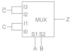
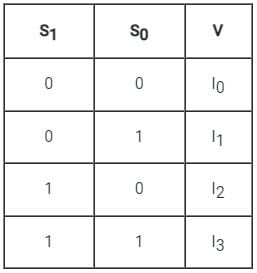
A 4 × 1 Multiplexer is shown in the Figure below. The output Z is
a)
A NOR C
b)
B NOR C
c)
B XOR C
d)
A XOR C
|
|
Sudhir Patel answered |
Concept:
In a 4 × 1 MUX
Truth-Table is given as:
Truth-Table is given as:
Y = Output = S̅1 S̅0 I0 + S̅1 S0 I1 + S1 S̅0 I2 + S1 S0 I3
MUX contains AND gate followed by OR gate
Calculation:
Given:
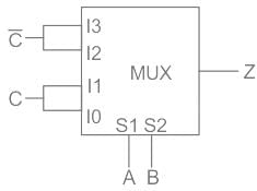
Z = Output = A̅B̅C + A̅BC + AB̅C̅ + ABC̅
Z = A̅C(B̅ + B) + AC̅(B̅ + B)
Z = A̅C + AC̅
Z = A XOR C
Hence, option 4 is correct.
MUX contains AND gate followed by OR gate
Calculation:
Given:
Z = Output = A̅B̅C + A̅BC + AB̅C̅ + ABC̅
Z = A̅C(B̅ + B) + AC̅(B̅ + B)
Z = A̅C + AC̅
Z = A XOR C
Hence, option 4 is correct.
Which of the following is a combinational logic circuit that has 2n input lines and a single output line?- a)Demultiplexer
- b)Decoder
- c)Encoder
- d)Multiplexer
Correct answer is option 'D'. Can you explain this answer?
Which of the following is a combinational logic circuit that has 2n input lines and a single output line?
a)
Demultiplexer
b)
Decoder
c)
Encoder
d)
Multiplexer
|
|
Naveen Shah answered |
Answer:
A combinational logic circuit is a digital circuit that produces an output based solely on the current inputs. It does not have any memory elements or feedback loops.
A multiplexer, also known as a data selector, is a combinational circuit that selects one of many inputs and forwards it to the output line based on the control inputs. It has 2n input lines, where n is the number of control inputs, and a single output line.
Explanation:
Let's analyze the given options and their characteristics:
a) Demultiplexer: A demultiplexer takes a single input line and routes it to one of the 2n output lines based on the control inputs. It has n control inputs and 2n output lines. Therefore, it does not match the given criteria of having 2n input lines.
b) Decoder: A decoder takes n input lines and produces 2n output lines. It activates one of the output lines based on the binary value of the input lines. It does not have 2n input lines and a single output line, so it is not the correct answer.
c) Encoder: An encoder takes 2n input lines and produces n output lines. It encodes the binary value of the input lines into an equivalent value on the output lines. It does not have 2n input lines and a single output line, so it is not the correct answer.
d) Multiplexer: A multiplexer takes 2n input lines and forwards one of them to the output line based on the control inputs. It has n control inputs and a single output line. It matches the given criteria of having 2n input lines and a single output line, so it is the correct answer.
Therefore, the correct answer is option 'D' - Multiplexer.
Which of the following are building blocks of encoders?- a)NOT gate
- b)OR gate
- c)AND gate
- d)NAND gate
Correct answer is option 'B'. Can you explain this answer?
Which of the following are building blocks of encoders?
a)
NOT gate
b)
OR gate
c)
AND gate
d)
NAND gate
|
|
Aniket Kulkarni answered |
Building Blocks of Encoders
Encoders are digital electronic devices that are used to convert information from one format to another. They are widely used in digital systems to convert analog signals into digital signals. The basic function of an encoder is to encode the input signals into binary code.
Building blocks of encoders include:
1. NOT gate:
A NOT gate, also known as an inverter, is a basic logic gate that has one input and one output. It produces the logical complement of the input signal. In an encoder, a NOT gate can be used to invert the input signal before it is encoded.
2. OR gate:
An OR gate is a logic gate that takes multiple inputs and produces a logical OR of those inputs at its output. It outputs a high signal if any of the inputs are high. In an encoder, an OR gate can be used to combine multiple input signals and generate a single output signal.
3. AND gate:
An AND gate is a logic gate that takes multiple inputs and produces a logical AND of those inputs at its output. It outputs a high signal only if all of the inputs are high. In an encoder, an AND gate can be used to combine multiple input signals and generate a single output signal.
4. NAND gate:
A NAND gate is a logic gate that is a combination of an AND gate followed by a NOT gate. It takes multiple inputs and produces the logical complement of the logical AND of those inputs at its output. In an encoder, a NAND gate can be used to combine multiple input signals and generate a single output signal.
Correct Answer: Option 'B' (OR gate)
Explanation:
The correct answer is option 'B' because an OR gate is one of the essential building blocks of an encoder. It is used to combine multiple input signals and generate a single output signal. An encoder typically has multiple inputs and a single output, where each input represents a different information bit. The OR gate is used to combine these input signals and generate the encoded output.
A decoder converts n inputs to __________ outputs.- a)n
- b)n2
- c)2n
- d)nn
Correct answer is option 'C'. Can you explain this answer?
A decoder converts n inputs to __________ outputs.
a)
n
b)
n2
c)
2n
d)
nn
|
|
Sudhir Patel answered |
Decoder is a circuit with n input lines and 2n output lines.
A digital multiplexer is a combinational circuit that selects _________.- a)One digital information from several sources and transmits the selected one
- b)Many digital information and convert them into one
- c)Many decimal inputs and transmits the selected information
- d)Many decimal outputs and accepts the selected information
Correct answer is option 'A'. Can you explain this answer?
A digital multiplexer is a combinational circuit that selects _________.
a)
One digital information from several sources and transmits the selected one
b)
Many digital information and convert them into one
c)
Many decimal inputs and transmits the selected information
d)
Many decimal outputs and accepts the selected information
|
|
Sudhir Patel answered |
A digital multiplexer is a combinational circuit that selects one digital information from several sources and transmits the selected information on a single output line depending on the status of the select lines. That is why it is also known as a data selector.
The device shown here is most likely a ________
- a)Comparator
- b)Multiplexer
- c)Inverter
- d)Demultiplexer
Correct answer is option 'D'. Can you explain this answer?
The device shown here is most likely a ________
a)
Comparator
b)
Multiplexer
c)
Inverter
d)
Demultiplexer
|
|
Yash Patel answered |
The given diagram is demultiplexer, because it takes single input & gives many outputs. A demultiplexer is a combinational circuit that takes a single output and latches it to multiple outputs depending on the select lines.
Which of the following can be represented for decoder?- a)Sequential circuit
- b)Combinational circuit
- c)Logical circuit
- d)None of the mentioned
Correct answer is option 'B'. Can you explain this answer?
Which of the following can be represented for decoder?
a)
Sequential circuit
b)
Combinational circuit
c)
Logical circuit
d)
None of the mentioned
|
|
Sudhir Patel answered |
Combinational circuit in which output depends only on the state of inputs.
It is possible for an enable or strobe input to undergo an expansion of two or more MUX ICs to the digital multiplexer with the proficiency of large number of ___________- a)Inputs
- b)Outputs
- c)Selection lines
- d)Enable lines
Correct answer is option 'A'. Can you explain this answer?
It is possible for an enable or strobe input to undergo an expansion of two or more MUX ICs to the digital multiplexer with the proficiency of large number of ___________
a)
Inputs
b)
Outputs
c)
Selection lines
d)
Enable lines
|
|
Sudhir Patel answered |
It is possible for an enable or strobe input to undergo an expansion of two or more MUX ICs to the digital multiplexer with the proficiency of large number of inputs.
Any combinational circuit can be designed using only- a)AND gates
- b)OR gates
- c)XOR gates
- d)NOR gates
Correct answer is option 'D'. Can you explain this answer?
Any combinational circuit can be designed using only
a)
AND gates
b)
OR gates
c)
XOR gates
d)
NOR gates
|
|
Ravi Singh answered |
Concept:
A universal gate is the one with which any other Boolean function can be implemented without the need of other gates.
A universal gate is the one with which any other Boolean function can be implemented without the need of other gates.
Explanation:
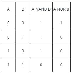
Two universal gates are NAND and NOR.
NAND:
In this gate, output of logic gate is false only when both the inputs are true. It is the complement of AND gate.
NOR gate: Output of this logic gate is true when both inputs are false.
Truth Table:
Two universal gates are NAND and NOR.
NAND:
In this gate, output of logic gate is false only when both the inputs are true. It is the complement of AND gate.
NOR gate: Output of this logic gate is true when both inputs are false.
Truth Table:
Which combinational circuit is renowned for selecting a single input from multiple inputs & directing the binary information to output line?- a)Data Selector
- b)Data distributor
- c)Both data selector and data distributor
- d)DeMultiplexer
Correct answer is option 'A'. Can you explain this answer?
Which combinational circuit is renowned for selecting a single input from multiple inputs & directing the binary information to output line?
a)
Data Selector
b)
Data distributor
c)
Both data selector and data distributor
d)
DeMultiplexer
|
|
Sudhir Patel answered |
Data Selector is another name of Multiplexer. A multiplexer (or MUX) is a device that selects one of several analog or digital input signals and forwards the selected input into a single line, depending on the active select lines.
Chapter doubts & questions for Combinational Circuits - 6 Months Preparation for GATE CSE 2025 is part of Computer Science Engineering (CSE) exam preparation. The chapters have been prepared according to the Computer Science Engineering (CSE) exam syllabus. The Chapter doubts & questions, notes, tests & MCQs are made for Computer Science Engineering (CSE) 2025 Exam. Find important definitions, questions, notes, meanings, examples, exercises, MCQs and online tests here.
Chapter doubts & questions of Combinational Circuits - 6 Months Preparation for GATE CSE in English & Hindi are available as part of Computer Science Engineering (CSE) exam.
Download more important topics, notes, lectures and mock test series for Computer Science Engineering (CSE) Exam by signing up for free.
6 Months Preparation for GATE CSE
453 videos|1305 docs|700 tests
|
|
© EduRev
|
Education Revolution
|


|


Signup to see your scores
go up
within 7 days!
within 7 days!
Takes less than 10 seconds to signup