


All Exams >
Electrical Engineering (EE) >
6 Months Preparation for GATE Electrical >
All Questions
All questions of State Space Analysis for Electrical Engineering (EE) Exam
For a linear time invariant system, an optimal controller can be designed if- a)the system is unstable but observable
- b)the system is controllable and observable
- c)the system is stable and unobservable
- d)the system is uncontrollable but stable
Correct answer is option 'B'. Can you explain this answer?
For a linear time invariant system, an optimal controller can be designed if
a)
the system is unstable but observable
b)
the system is controllable and observable
c)
the system is stable and unobservable
d)
the system is uncontrollable but stable
|
|
Ishani Iyer answered |
An optimal controller for an LTI system can be designed provided the system is both controllable and observable

The eigen values of linear system are the location of- a)zeros of the system
- b)poles of the system
- c)both (a) and (b)
- d)finite poles and zeros
Correct answer is option 'B'. Can you explain this answer?
The eigen values of linear system are the location of
a)
zeros of the system
b)
poles of the system
c)
both (a) and (b)
d)
finite poles and zeros
|
|
Avik Saha answered |
Eigen value are given by | sI- A I = 0, which is the location of poles.
Consider the following statements related to state space analysis of control systems:
1. The zeros of the system can be obtained from eigen value of the system matrix.
2. A system is said to be observable if every state x0 can be exactly determined from the measurement of the output ‘y’ over a finite interval of time 0 ≤ t ≤ tf.
3. The process by which transfer function changes to state diagram or state equations is called decomposition of the transfer function.
4. The state space techniques can be applied to linear and time invariant systems only.Which of the above statements are correct?- a)1, 3 and 4
- b)1, 2 and 3
- c)2 and 3
- d)2, 3 and 4
Correct answer is option 'C'. Can you explain this answer?
Consider the following statements related to state space analysis of control systems:
1. The zeros of the system can be obtained from eigen value of the system matrix.
2. A system is said to be observable if every state x0 can be exactly determined from the measurement of the output ‘y’ over a finite interval of time 0 ≤ t ≤ tf.
3. The process by which transfer function changes to state diagram or state equations is called decomposition of the transfer function.
4. The state space techniques can be applied to linear and time invariant systems only.
Which of the above statements are correct?
a)
1, 3 and 4
b)
1, 2 and 3
c)
2 and 3
d)
2, 3 and 4
|
|
Rajat Kumar answered |
1. The first statement is incorrect. The zeros of a system are not obtained from the eigenvalues of the system matrix. Zeros are the values of the input for which the output of the system becomes zero. They can be determined by setting the transfer function of the system equal to zero and solving for the input.
2. The second statement is also incorrect. Observability is a property of a system that determines whether the states of the system can be determined or estimated from the measurements of the output. It does not refer to the ability to determine a specific initial state x0 from the output. Observability can be checked using the observability matrix, which is constructed using the system matrices and determines if the system is observable or not.
2. The second statement is also incorrect. Observability is a property of a system that determines whether the states of the system can be determined or estimated from the measurements of the output. It does not refer to the ability to determine a specific initial state x0 from the output. Observability can be checked using the observability matrix, which is constructed using the system matrices and determines if the system is observable or not.


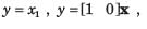
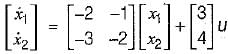
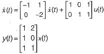
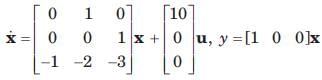
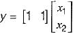
The system equations are given by
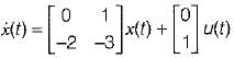
y(t) = [1 0]x(t)
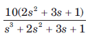
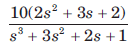
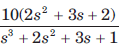
The transfer function of the above system is- a)

- b)
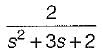
- c)

- d)

Correct answer is option 'A'. Can you explain this answer?
The system equations are given by
y(t) = [1 0]x(t)
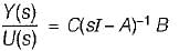
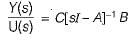
The transfer function of the above system is
y(t) = [1 0]x(t)
The transfer function of the above system is
a)
b)
c)
d)
|
|
Alok Verma answered |
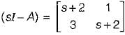
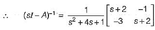
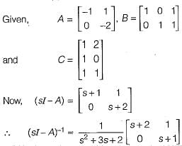
Given,
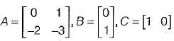
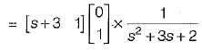
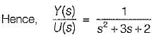
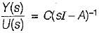
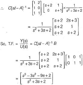
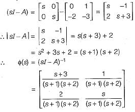
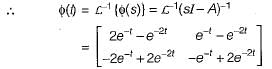
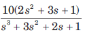
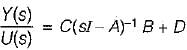
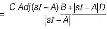
Transfer function of the given system is
Now,
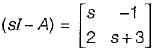
∴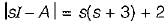
= s2 + 3s + 2
Now,
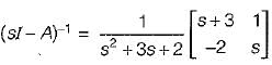
Now,
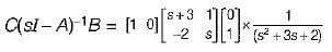

Transfer function of the given system is
Now,
∴
= s2 + 3s + 2
Now,
Now,
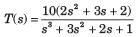
The transfer function of the system shown below is
- a)

- b)

- c)

- d)none of these
Correct answer is option 'A'. Can you explain this answer?
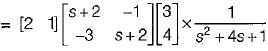
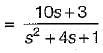
The transfer function of the system shown below is
a)
b)
c)
d)
none of these
|
|
Hiral Kulkarni answered |
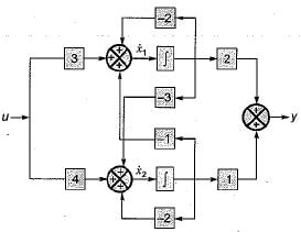
From given block diagram, the state equations can be written as:
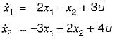
Also, output equation is
y = 2x1 + x2
In matrix form, we have:
and y = [2 1]x(t)
Now,
∴ Transfer function,
Also, output equation is
y = 2x1 + x2
In matrix form, we have:
and y = [2 1]x(t)
Now,
∴ Transfer function,
The state variable description of an autonomous system is, X = AX where X is a two-dimensional vector and A is a matrix given by

The eigen values of A are- a)jω and σ + jω
- b)σ + jω and σ - jω
- c)σ - jω and σ + jω
- d)σ - jω and jω
Correct answer is option 'B'. Can you explain this answer?
The state variable description of an autonomous system is, X = AX where X is a two-dimensional vector and A is a matrix given by
The eigen values of A are
The eigen values of A are
a)
jω and σ + jω
b)
σ + jω and σ - jω
c)
σ - jω and σ + jω
d)
σ - jω and jω
|
|
Pankaj Mehta answered |
Eigen values of A are given by
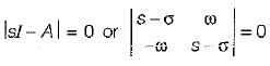
or, (s - σ)2 + ω2 = 0
or, s = σ ± jω
or, s = σ + jω and s = σ - jω
or, (s - σ)2 + ω2 = 0
or, s = σ ± jω
or, s = σ + jω and s = σ - jω
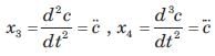
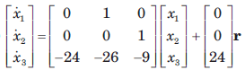
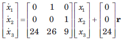
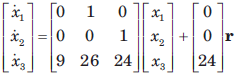
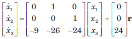
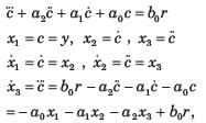
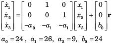
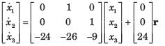
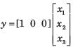
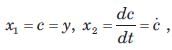
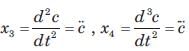
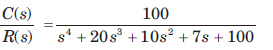
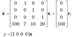
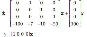
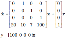
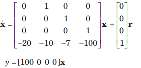
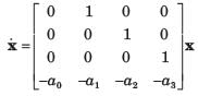
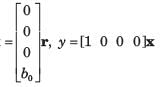
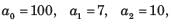
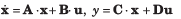
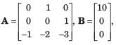
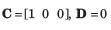
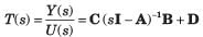
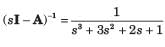
Determine the state-space representation for the transfer function given in question. Choose the state variable as follows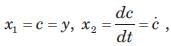
 Q.
Q. 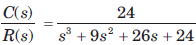
- a)
- b)
- c)
- d)
Correct answer is option 'A'. Can you explain this answer?
Determine the state-space representation for the transfer function given in question. Choose the state variable as follows
Q.
a)
b)
c)
d)

|
Sneha Roy answered |
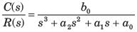
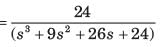
(s3 + a2s2 + a1s + a0)C(s) = b0R(s)
Taking the inverse Laplace transform assuming zero initial conditions


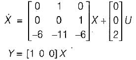
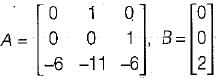
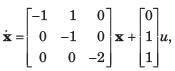
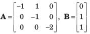
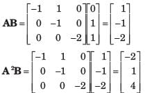
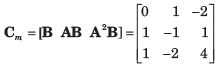
Consider the system shown in fig.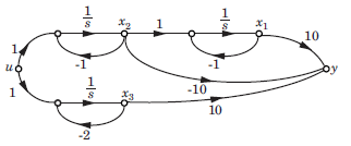 Q. The system is
- a)Controllable and observable
- b)Controllable only
- c)Observable only
- d)None of the above
Correct answer is option 'A'. Can you explain this answer?
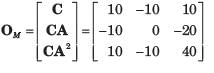
Consider the system shown in fig.
Q. The system is
a)
Controllable and observable
b)
Controllable only
c)
Observable only
d)
None of the above

|
Bijoy Mehra answered |
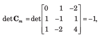
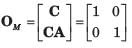
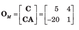
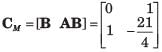
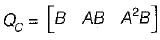
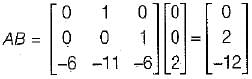
Since the determinant is not zero, the 3 x 3 matrix is nonsingular and system is controllable
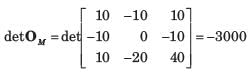
The rank of OM is 3. Hence system is observable.
Consider the network shown in fig.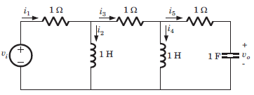 Q. The state variable may be
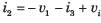
- a)i2 , i4
- b)i2 , i4 , vo
- c)i1 , i3
- d)i1 , i3 , i5
Correct answer is option 'B'. Can you explain this answer?
Consider the network shown in fig.
Q. The state variable may be
a)
i2 , i4
b)
i2 , i4 , vo
c)
i1 , i3
d)
i1 , i3 , i5

|
Moumita Chopra answered |
There are three energy storage elements, hence 3 variable. i2 ,i4 and vo are available in differentiated form hence these are state variable.


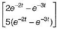
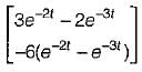
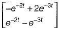
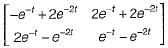
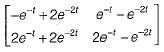
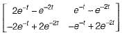
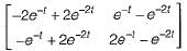
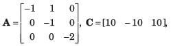
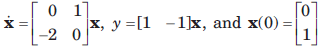
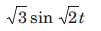
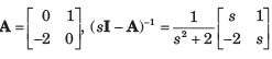
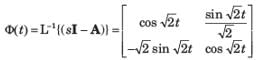
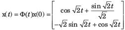
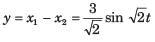
Consider the following matrix:
x(t) is given by - a)
- b)
- c)
- d)

Correct answer is option 'B'. Can you explain this answer?
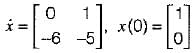
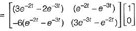
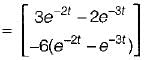
Consider the following matrix:
x(t) is given by
x(t) is given by
a)
b)
c)
d)
|
|
Arindam Sengupta answered |
Given,
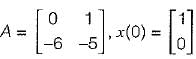
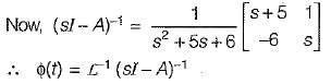
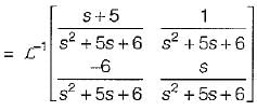
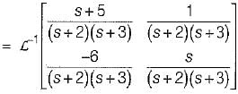
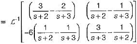
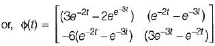
So, x(t) = ϕ(t).x(0)
= state transition equation
So, x(t) = ϕ(t).x(0)
= state transition equation

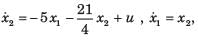
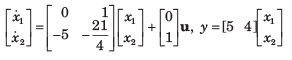
The state-variable description of a linear autonomous system is  is a two-dimensional state vector and A is a matrix given by

The poles of the system are located at
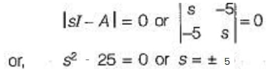
- a)- 5 and +5
- b)- 5j and +5j
- c)-5 and -5
- d)+5 and +5
Correct answer is option 'A'. Can you explain this answer?
The state-variable description of a linear autonomous system is is a two-dimensional state vector and A is a matrix given by
is a two-dimensional state vector and A is a matrix given by The poles of the system are located at
a)
- 5 and +5
b)
- 5j and +5j
c)
-5 and -5
d)
+5 and +5
|
|
Prisha Sen answered |
Poles of given system are given by
A state flow graph is shown in fig.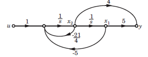 The system is
- a)Observable and controllable
- b)Controllable only
- c)Observable only
- d)None of the above
Correct answer is option 'B'. Can you explain this answer?
A state flow graph is shown in fig.
The system is
a)
Observable and controllable
b)
Controllable only
c)
Observable only
d)
None of the above

|
Diya Patel answered |
det OM = 0. Thus system is not observable
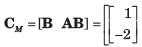
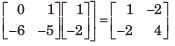
det CM = -1. Thus system is controllable.
det CM = -1. Thus system is controllable.
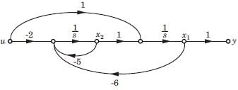
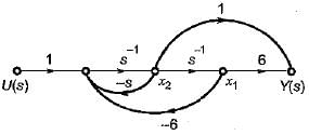
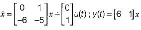
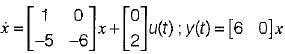
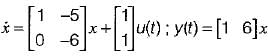
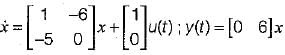
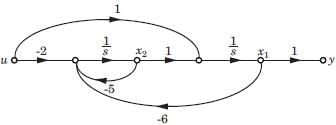
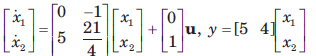
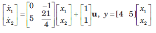
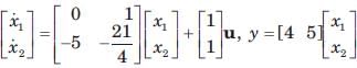
The state space representation of the system represented by the SFG shown below is
- a)
- b)
- c)
- d)
Correct answer is option 'A'. Can you explain this answer?
The state space representation of the system represented by the SFG shown below is
a)
b)
c)
d)
|
|
Bijoy Mehta answered |
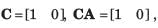
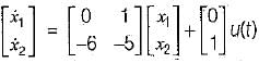
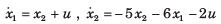
The state equations from the given signal flow graph can be written as:
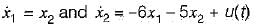
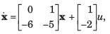
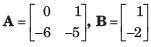
In matrix form,
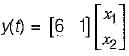
Also, output is
y(t) = 6x1 + x2
In matrix form
In matrix form,
Also, output is
y(t) = 6x1 + x2
In matrix form
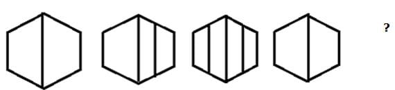
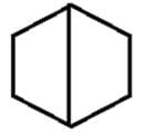
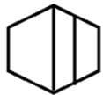
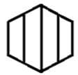
Complete the given series from the options given below.
- a)

- b)

- c)

- d)

Correct answer is option 'C'. Can you explain this answer?
Complete the given series from the options given below.
a)
b)
c)
d)
|
|
Arpeet Subudhi answered |
The answer is option 'C' because according to the given series the blue box will come after the red box.

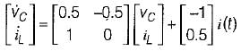
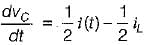
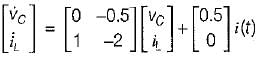
Consider the network shown in fig. The state-space representation for this network is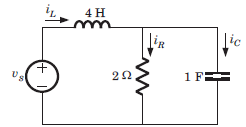
- a)
- b)
- c)
- d)
Correct answer is option 'B'. Can you explain this answer?
Consider the network shown in fig. The state-space representation for this network is
a)
b)
c)
d)

|
Varun Banerjee answered |
vc and iL are state variable.
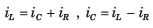
Hence equation are
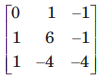
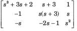
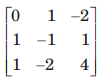
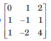
If the system matrix of a linear time invariant continuous system is given by 
its characteristic equation will be given by- a)s2 + 5s + 2 = 0
- b)S2 - 2s - 5 = 0
- c)s2 + s + 3 = 0
- d)s2 + 2s + 5 = 0
Correct answer is option 'A'. Can you explain this answer?
If the system matrix of a linear time invariant continuous system is given by
its characteristic equation will be given by
its characteristic equation will be given by
a)
s2 + 5s + 2 = 0
b)
S2 - 2s - 5 = 0
c)
s2 + s + 3 = 0
d)
s2 + 2s + 5 = 0
|
|
Nishtha Chauhan answered |
Characteristic equation is
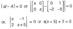
or, s2 + 5s + 2 = 0
or, s2 + 5s + 2 = 0

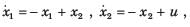
The state variable representation of a system is given by:
The system is- a)neither controllable nor observable
- b)controllable but not observable
- c)uncontrollable but observable
- d)both controiiabie and observable
Correct answer is option 'D'. Can you explain this answer?
The state variable representation of a system is given by:
The system is
The system is
a)
neither controllable nor observable
b)
controllable but not observable
c)
uncontrollable but observable
d)
both controiiabie and observable
|
|
Manoj Chaudhary answered |
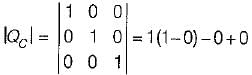
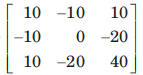
Here,
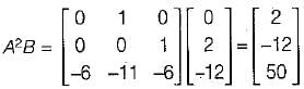
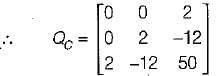
So, IQCI = 0 - 0 + 2(0 - 4)
= - 8 ≠ 0
Hence, the system is controllable.
Also, Q0 = [CT ATCT (AT)2 CT]
Here,
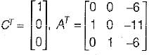
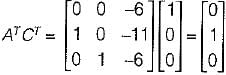
and
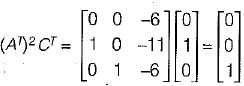
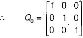
So,
= 1 ≠ 0
Since |Q0| ≠ 0, therefore given system is observable.


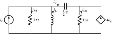
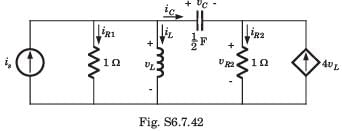
Consider the network shown in fig. This system may be represented in state space representation 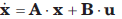
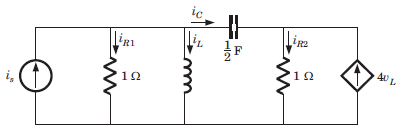 Q. The state variable may be
- a)iR1 , iR2
- b)iL , iC
- c)vC , iL
- d)None of the above
Correct answer is option 'C'. Can you explain this answer?
Consider the network shown in fig. This system may be represented in state space representation
Q. The state variable may be
a)
iR1 , iR2
b)
iL , iC
c)
vC , iL
d)
None of the above

|
Kritika Shah answered |
Energy storage elements are capacitor and inductor. vC and iL are available in differential form and linearly independent. Hence vC and iL are suitable for state-variable.


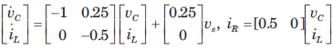
Consider the network shown in fig. This system may be represented in state space representation Q. If state variable are chosen as in previous question, then the matrix A is - a)

- b)

- c)

- d)

Correct answer is option 'B'. Can you explain this answer?
Consider the network shown in fig. This system may be represented in state space representation
Q. If state variable are chosen as in previous question, then the matrix A is
a)
b)
c)
d)

|
Sagnik Sen answered |
 .....(i)
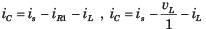 .....(ii)
Solving equation (i) and (ii)
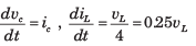
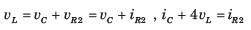
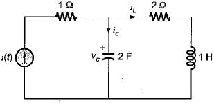
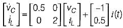
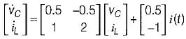
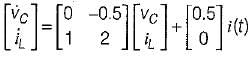
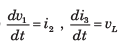
The state equation for the circuit shown below is
- a)
- b)
- c)
- d)
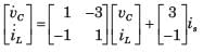
Correct answer is option 'C'. Can you explain this answer?
The state equation for the circuit shown below is
a)
b)
c)
d)
|
|
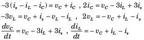
Hridoy Chakraborty answered |
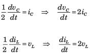
Let us select the state variables as Vc and iL.
Applying KVL in the mesh-2, we have:
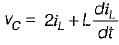
or,
 .............(1)
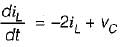
Also, by applying KCL at the given node, we get:
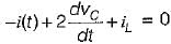
or,
 ..........(2)
From equations (1) and (2), state equations in matrix form can be written as:
Applying KVL in the mesh-2, we have:
or,
.............(1)Also, by applying KCL at the given node, we get:
or,
..........(2)From equations (1) and (2), state equations in matrix form can be written as:
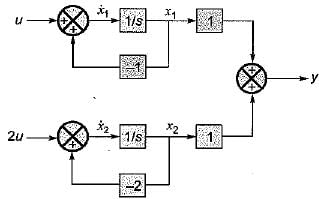
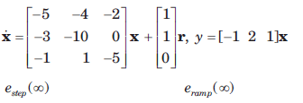
Consider the system shown in figure below:
The system is- a)controllable but unobservable
- b)uncontrollable but observable
- c)uncontrollable and unobservable
- d)controllable and observable
Correct answer is option 'D'. Can you explain this answer?
Consider the system shown in figure below:
The system is
The system is
a)
controllable but unobservable
b)
uncontrollable but observable
c)
uncontrollable and unobservable
d)
controllable and observable
|
|
Alok Roy answered |
From given block diagram, the state equations can be written as:
x1 = -x1 + u and x2 = -2x2 + 2u
in matrix form,
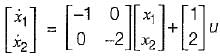
Also, y = x1 + x2
In matrix form,
Thus,
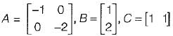
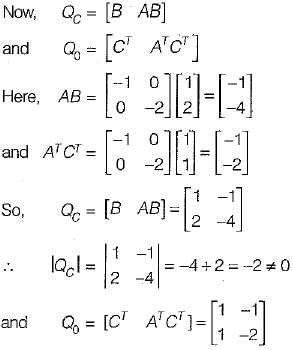
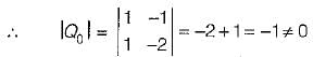
Since, |Qc| ≠ 0 and |Q0| ≠ 0, therefore given system is both controllable and observable.
x1 = -x1 + u and x2 = -2x2 + 2u
in matrix form,
Also, y = x1 + x2
In matrix form,
Thus,
Since, |Qc| ≠ 0 and |Q0| ≠ 0, therefore given system is both controllable and observable.
Which one of the following information is necessary to formulate the problem of control systems optimization?- a)System state equation, output equation, control vector and the performance index only.
- b)System state equation, output equation, control vector, constraints of the problem, the performance index and system parameters.
- c)System state equation, output equation, control vector and constraints of the problem only.
- d)System state equation, output equation and the control vector only.
Correct answer is option 'C'. Can you explain this answer?
Which one of the following information is necessary to formulate the problem of control systems optimization?
a)
System state equation, output equation, control vector and the performance index only.
b)
System state equation, output equation, control vector, constraints of the problem, the performance index and system parameters.
c)
System state equation, output equation, control vector and constraints of the problem only.
d)
System state equation, output equation and the control vector only.
|
|
Dhruba Rane answered |
The correct answer is option 'C' - System state equation, output equation, control vector, and constraints of the problem are necessary to formulate the problem of control systems optimization.
Explanation:
To formulate the problem of control systems optimization, we need several pieces of information. Let's break it down step by step:
1. System State Equation: The system state equation describes the dynamic behavior of the system and represents how the system's state variables evolve over time. It is essential for understanding the system's behavior and formulating the optimization problem.
2. Output Equation: The output equation relates the system's state variables to the system's output. It provides information on how the control inputs affect the system's output. This equation is necessary to define the desired performance of the system and formulate the optimization problem.
3. Control Vector: The control vector represents the inputs or control actions applied to the system. It consists of the variables that can be manipulated to achieve the desired system performance. The optimization problem aims to find the optimal values for the control vector, and therefore, it is essential to include it in the problem formulation.
4. Constraints of the Problem: The constraints of the problem define the limits or restrictions on the system's behavior or control inputs. These constraints could be physical limitations, safety requirements, or operational restrictions. Including the constraints in the problem formulation is crucial to ensure that the optimization solution satisfies all the necessary conditions.
5. Performance Index: The performance index quantifies the desired performance of the system. It is a function of the system's state, output, and control inputs. The optimization problem seeks to minimize or maximize this performance index by finding the optimal values for the control vector. Therefore, including the performance index in the problem formulation is crucial.
By considering all these factors, option 'C' - System state equation, output equation, control vector, and constraints of the problem provides all the necessary information to formulate the problem of control systems optimization.


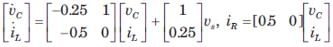
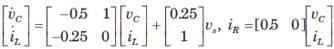
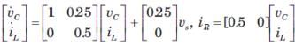
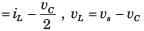
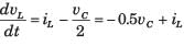
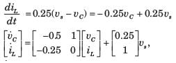
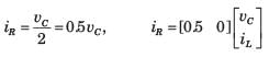
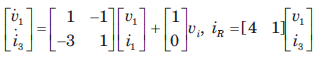
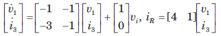
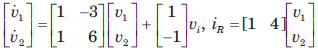
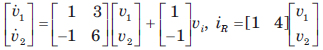
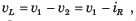
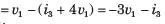
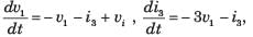
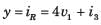
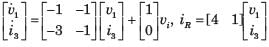
For the network shown in fig. The output is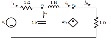 iR(t). The state space representation is
- a)
- b)
- c)
- d)
Correct answer is option 'B'. Can you explain this answer?
For the network shown in fig. The output is
iR(t). The state space representation is
a)
b)
c)
d)

|
Mrinalini Chavan answered |
Hence v1 and i3 are state variable.


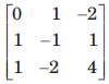
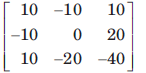
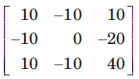
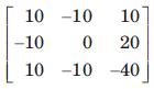
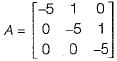
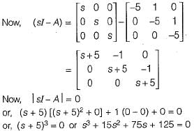
The system matrix of a continous time system is given by:
The characteristic equation is- a)s3 + 12s2 - 70s + 120 = 0
- b)s3 - 17s2 + 10s + 50 = 0
- c)s3 + s2 + 2s + 20 = 0
- d)s3 + 15s2 + 75s + 125 = 0
Correct answer is option 'D'. Can you explain this answer?
The system matrix of a continous time system is given by:
The characteristic equation is
The characteristic equation is
a)
s3 + 12s2 - 70s + 120 = 0
b)
s3 - 17s2 + 10s + 50 = 0
c)
s3 + s2 + 2s + 20 = 0
d)
s3 + 15s2 + 75s + 125 = 0
|
|
Raghav Majumdar answered |
The characteristic equation 
Consider the system shown in fig.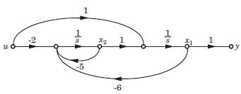 The system is
- a)Controllable and observable
- b)Controllable only
- c)Observable only
- d)None of the above
Correct answer is option 'C'. Can you explain this answer?
Consider the system shown in fig.
The system is
a)
Controllable and observable
b)
Controllable only
c)
Observable only
d)
None of the above

|
Bhaskar Unni answered |
det CM = 0. Hence system is not controllable. det OM = 1. Hence system is observable.

For arbitrary pole placement, the following combination is necessary.- a)State feedback and stability
- b)Output feedback and observability
- c)Output feedback and controllability
- d)State feedback and controllability
Correct answer is option 'D'. Can you explain this answer?
For arbitrary pole placement, the following combination is necessary.
a)
State feedback and stability
b)
Output feedback and observability
c)
Output feedback and controllability
d)
State feedback and controllability
|
|
Gargi Reddy answered |
Explanation:
To understand why the correct answer is option 'D', let's first understand the concepts of pole placement, state feedback, and controllability.
Pole Placement:
In control systems, pole placement is a technique used to assign the desired closed-loop poles of a system. By placing the poles at desired locations, we can control the system's dynamic behavior, such as its response time, stability, and transient response.
State Feedback:
State feedback is a control technique where the control input is a function of the system's state variables. It involves measuring the system's state variables, performing some calculations, and then using the result to generate the control signal.
Controllability:
Controllability refers to the ability to control the system's state variables using the available control inputs. A system is said to be controllable if it is possible to find a control input that can drive the system from any initial state to any desired state within a finite time.
Analysis of Options:
Let's analyze each option and determine its validity:
a) State feedback and stability:
State feedback alone is not sufficient for arbitrary pole placement. Stability is a separate concept that ensures the system's output remains bounded in the presence of bounded inputs. While state feedback can contribute to stability, it is not necessary for arbitrary pole placement.
b) Output feedback and observability:
Output feedback is a control technique where the control input is a function of the system's output. Observability, on the other hand, refers to the ability to estimate the system's state variables using the available output measurements. While output feedback can contribute to observability, it is not necessary for arbitrary pole placement.
c) Output feedback and controllability:
Output feedback alone is not sufficient for arbitrary pole placement. Controllability, as discussed earlier, ensures the ability to control the system's state variables using the available control inputs. Output feedback may help in achieving controllability, but it is not necessary for arbitrary pole placement.
d) State feedback and controllability:
This is the correct combination. State feedback provides a way to control the system's state variables, and controllability ensures that the system can be controlled from any initial state to any desired state. By combining state feedback and controllability, we can achieve arbitrary pole placement.
Conclusion:
The correct combination for arbitrary pole placement is state feedback and controllability. State feedback allows control over the system's state variables, and controllability ensures that the system can be controlled from any initial state to any desired state.
Assertion (A): The eigen values of a linear continuous-data time invariant system controls the stability of the system.
Reason (R): The roots of the characteristic equation are the same as the eigen values of system matrix A of the state equations.- a)Both A and R are true and R is a correct explanation of A.
- b)Both A and R are true but R is not a correct explanation of A.
- c)A is true but R is false.
- d)A is false but R is true.
Correct answer is option 'A'. Can you explain this answer?
Assertion (A): The eigen values of a linear continuous-data time invariant system controls the stability of the system.
Reason (R): The roots of the characteristic equation are the same as the eigen values of system matrix A of the state equations.
Reason (R): The roots of the characteristic equation are the same as the eigen values of system matrix A of the state equations.
a)
Both A and R are true and R is a correct explanation of A.
b)
Both A and R are true but R is not a correct explanation of A.
c)
A is true but R is false.
d)
A is false but R is true.
|
|
Kavya Singhania answered |
Assertion (A): The eigen values of a linear continuous-data time invariant system controls the stability of the system.
Reason (R): The roots of the characteristic equation are the same as the eigen values of system matrix A of the state equations.
To determine whether the given assertion and reason are true or false, let's analyze each statement individually.
Statement A: The eigen values of a linear continuous-data time invariant system control the stability of the system.
Explanation:
In control theory, the stability of a system is a crucial property that determines whether the system will exhibit bounded or unbounded behavior over time. A system is considered stable if its response remains bounded for all bounded inputs.
Eigenvalues are a fundamental concept in linear algebra and are used to analyze the behavior of linear systems. In the context of control systems, the eigenvalues of the system matrix A play a crucial role in determining the stability of the system.
The eigenvalues of A can be obtained by solving the characteristic equation det(sI - A) = 0, where s is a complex variable and I is the identity matrix. The solutions to this equation are the eigenvalues of A.
For a linear continuous-data time invariant system, the eigenvalues of A can be classified into three categories based on their location in the complex plane:
1. Stable: If all the eigenvalues have negative real parts, then the system is stable. The system's response will decay over time, and any bounded input will result in a bounded output.
2. Unstable: If at least one eigenvalue has a positive real part, then the system is unstable. The system's response will grow exponentially over time, and even a bounded input can lead to an unbounded output.
3. Marginally stable: If the eigenvalues have zero real parts and are purely imaginary, the system is marginally stable. The response neither decays nor grows exponentially but oscillates indefinitely.
Therefore, the assertion that the eigenvalues of a linear continuous-data time invariant system control the stability of the system is true.
Statement R: The roots of the characteristic equation are the same as the eigenvalues of system matrix A of the state equations.
Explanation:
The characteristic equation of a linear continuous-data time invariant system is obtained by setting the determinant of the matrix (sI - A) equal to zero, where s is a complex variable and A is the system matrix. The roots of this equation are referred to as the characteristic roots or eigenvalues of the system.
The eigenvalues of the system matrix A are obtained by solving the characteristic equation. The eigenvalues represent the poles of the transfer function of the system, which describe its dynamic behavior.
Hence, the reason that the roots of the characteristic equation are the same as the eigenvalues of system matrix A of the state equations is true.
Conclusion:
Both the assertion and the reason are true, and the reason is a correct explanation of the assertion. The eigenvalues of a linear continuous-data time invariant system indeed control the stability of the system, and the roots of the characteristic equation correspond to the eigenvalues of the system matrix A.
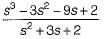
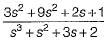
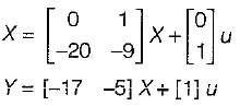
The zeros of following system are located at
- a)-4 and - 5
- b)-1 and -4
- c)-1 and -3
- d)-3 and -5
Correct answer is option 'C'. Can you explain this answer?
The zeros of following system are located at
a)
-4 and - 5
b)
-1 and -4
c)
-1 and -3
d)
-3 and -5
|
|
Kunal Sharma answered |
T.F.,
Hence, zeros are at:
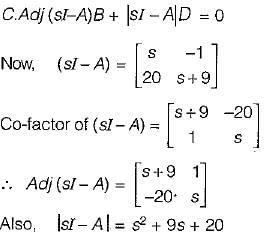
So, zeros are at:
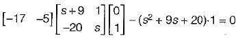
or, -17 -5s + s2 + 9s + 20 = 0
or, s2 + 4s + 3 = 0
or, (s+1) (s+3) = 0
or, s = -1,- 3
Hence, zeros are at:
So, zeros are at:
or, -17 -5s + s2 + 9s + 20 = 0
or, s2 + 4s + 3 = 0
or, (s+1) (s+3) = 0
or, s = -1,- 3
Chapter doubts & questions for State Space Analysis - 6 Months Preparation for GATE Electrical 2025 is part of Electrical Engineering (EE) exam preparation. The chapters have been prepared according to the Electrical Engineering (EE) exam syllabus. The Chapter doubts & questions, notes, tests & MCQs are made for Electrical Engineering (EE) 2025 Exam. Find important definitions, questions, notes, meanings, examples, exercises, MCQs and online tests here.
Chapter doubts & questions of State Space Analysis - 6 Months Preparation for GATE Electrical in English & Hindi are available as part of Electrical Engineering (EE) exam.
Download more important topics, notes, lectures and mock test series for Electrical Engineering (EE) Exam by signing up for free.
6 Months Preparation for GATE Electrical
675 videos|1297 docs|786 tests
|
|
© EduRev
|
Education Revolution
|


|


Signup to see your scores
go up
within 7 days!
within 7 days!
Takes less than 10 seconds to signup